Construction Equipments and Tools - An Overview
Field Applicability and Utility
Introduction
Construction activity being the second most important activity next to agriculture in India, it also is an integral part of a country's infrastructure and industrial development. It includes hospitals, schools, townships, offices, houses and other buildings; urban infrastructure; highways, roads, ports, railways, airports; power systems; irrigation and agriculture systems; telecommunications etc. Besides, the construction industry generates ample employment and provides a growth impulsion to other sectors through backward integration. It is, essential therefore, that, this vital activity is fostered for the healthy growth of the economy.
For the successful execution of any project, effective planning is essential right from conceptual stage till completion. In the present circumstances, with the help of advanced technologies, construction industry is heading towards a more mechanised scenario. Myriad options in terms of equipment availability are available and it becomes imperative to understand the performance characteristics of different types of construction equipments. Mechanisation also leads to improvement in quality, increase in productivity, less dependence on labour and speedy performance. This article presents an overview of construction equipment to give an extra edge to the reader and equip him with the necessary knowledge.
Knowledge of construction equipment is necessary to optimize the construction activity and enhance the productivity. The selection of equipment however depends on many criteria which are not discussed here. This article gives an overview of various construction equipments that are available in the industry today. Indicative usage of construction equipment is shown in Figure 1.
Figure 1: Indicative Usage of Construction Equipment
Challenges Faced By the Industry
The construction sector in India is currently facing a number of challenges. The Reserve Bank of India (RBI) raised benchmark interest rates on multiple occasions since March 2010 which increased the overall cost of borrowing. In addition, the private sector deferred its capital expenditure decisions on account of uncertain demand conditions and issues concerning land acquisition; approvals and clearances; fuel security and pricing; counterparty credit risks and policy issues. In FY 11, new projects announcements by the government sector also slowed down due to delays in decision making; lack of stable leadership at key public sector undertakings (PSUs); corruption-related investigations and state elections.
A key area of concern is the steady increase in the quantum of stalled projects to Rs. 4.17 trillion in September 2011from Rs. 2.94 trillion in September 2010, representing a 42% increase on a y-o-y basis (15% on q-o-q basis). Consequently, the y-o-y revenue growth of construction companies in Q1/Q2 FY 12 has been the slowest as compared to the past few years. The reduced pace of execution is also evidenced by the significantly lower y-o-y growth of 2.7% (at FY 05 prices) in construction GDP in H1 FY 12 as compared to 7.2% y-o-y growth in H1 FY 11.
The Cost of Equipment in a construction project varies from 10 to 30% of the total project depending upon the extent and nature of work. Projects involving for example, climbing Forms, will not fall into this generalised category. Meticulous planning with proper understanding of the equipment, selection, procurement, installation, operation, and maintenance play an important role in the completion of the project. The role of construction equipments in roads, highways, large building, dams, canal etc., will play important role.
Equipment Classification
Depending on the nature of activity and performance construction equipments can be classified as; Table 1 shows general classification of construction equipment.
- Excavating and Earth-moving equipment
- Hauling equipment
- Hoisting equipment
- Conveying equipment
- Aggregate and concrete production equipment
- Pile-driving equipment
- Tunneling and rock drilling equipment
- Pumping and dewatering equipment
Table1: General Equipment Classification
EXCAVATING AND EARTH MOVING EQUIPMENT
In any construction project, earth related operations can be listed as under;
- Excavation
- Transportation of excavated earth
- Placement
- Compacting
- Leveling
- Dozing
- Grading
- Hauling
1. Power shovel
Power Shovels are generally used to excavate the earth and to load the trucks and are capable of excavating all types of earth except hard rock. Size of the buckets varies from 0.375m3 to 5m3. Basics parts of power shovel include the track system, cabin, cables, rack, stick, boom foot-pin, saddle block, boom, boom point sheaves and bucket.
Power Shovels are suitable for close range of work and are capable of digging very hard materials including big sized boulders. It is used in various types of jobs such as digging in gravel banks, clay pits, digging cuts in road works, road-side berms, etc.
However, the following factors affect the output of the equipment;
- Class of material
- Depth of cutting
- Angle of swing
- Job condition
- Management condition
- Size of hauling units
- Skill of the operator
- Physical condition of the shovel
2. Back hoe
The backhoe, as equipment specialized in excavation consists of a boom, dipper stick, and bucket mounted on a tractor. Backhoes are typically used in trenching because they can excavate to a considerable depth below their base. This characteristic also makes them useful for work such as channel excavation, because the excavation can be done while the tractor remains on dry land. The primary disadvantage of using a backhoe in trenching work is that it cannot dig as clean a trench bottom as dedicated trenching equipment. Therefore, a skilled operator along with additional manual labor will be needed to shape the trench bottom after the backhoe finishes the excavation.
Like bulldozers, backhoes are typically categorized by their mountings. Backhoes are mounted on either rubber tires or crawler tracks. There are advantages to each type of mounting. Rubber-tired backhoes (also called backhoe/loaders) are more maneuverable, and can travel more quickly from one place to another. In addition, most rubber-tired backhoes have a loader bucket attached to the front of the tractor, allowing it to be used for work other than excavation. Crawler-track backhoes can be larger than rubber-tired backhoes, and they are better able to work on soft soils because of the larger surface area of the tracks.
The boom on a rubber-tired backhoe is mounted at the rear of the tractor. The boom swings horizontally at its base, and can cover an arc of approximately 180°. Some rubber-tired backhoes have offset booms to allow them to work along guardrails or walls. When the backhoe is working, the weight of the machine plus the soil in the bucket can make it unstable, especially as the boom swings to the side. To stabilize the backhoe, it is equipped with outrigger, stabilizing feet. These feet are located at the rear of the backhoe to carry the weight of the working end. When extended, the feet span an area wider than the tractor itself, and they rest at right angles to the trench. This stabilizes the backhoe, ensuring that it will not tip over during operation. The stabilizing feet should always be extended before beginning excavation.
3. Drag liners
The drag line is so named because of its prominent operation of dragging the bucket against the material to be dug. Unlike the shovel, it has a long light crane boom and the bucket is loosely attached to the boom through cables. Because of this construction, a dragline can dig and dump over larger distances than a shovel can do. Drag lines are useful for digging below its track level and handling softer materials. The basic parts of a drag line including the boom, hoist cable, drag cable, hoist chain, drag chain and bucket.
Being the most suitable machine for dragging softer material and below its track level, it is very useful for excavating trenches when the sides are permitted to establish their angle of repose without shoring. It has long reaches and hence very commonly used for canals and depositing the earth on the embankment without hauling units.
4. Clam shell
This is so named due to resemblance of its bucket to a clam which is like a shell-fish with hinged double shell. The front end is essentially a crane boom with a specially designed bucket loosely attached at the end through cables as in a drag line. The capacity of a clam shell bucket is usually given in cubic meters. The basic parts of clam shell bucket are the closing line, hoist line, sheaves, brackets, tagline, shell and hinge.
Used for handling loose material such as crushed stone, sand, gravel, coal etc. Main feature is vertical lifting of material from one location to another. Mainly used for removing material from coffer dam, sewer main holes, well foundations etc.
|
S.NO.
|
ITEMS OF COMPARISON
|
POWER SHOVEL
|
BACK HOE
|
DRAG LINE
|
CLAM SHELL
|
|
1
|
Excavation in hard
soil or rock
|
Good
|
Good
|
Not good
|
Poor
|
|
2
|
Excavation in wet
soil or mud
|
Poor
|
Poor
|
Moderately
good
|
Moderately
good
|
|
3
|
Distance between
footing and digging
|
Small
|
Small
|
Long
|
Long
|
|
4
|
Loading efficiency
|
Very good
|
Good
|
Moderately
good
|
Precise but
slow
|
|
5
|
Footing required
|
Close to work
|
Close to pit
|
Fairly away
from pit
|
Fairly away
from pit
|
|
6
|
Digging level
|
Digs at or above
footing level
|
Digs below
footing level
|
Digs below
footing level
|
Digs at or below
footing level
|
|
7
|
Cycle time
|
Short
|
Shortly more
than power shovel
|
More than
power shovel
|
More than the
other equipment
|
Comparison between different types of equipment is indicated in Table2
5. Scrapers
Scrapers, also known as pans, are machines designed to load, haul, and dump loose material. Scrapers can handle a variety of material, from fine-grained soils to rock left from blasting work. Scrapers are used in excavation and embankment work and in base course construction.
Scrapers consist of two components: the tractor, or prime mover, and the bowl. A typical tractor has two axles, with the bowl suspended from the frame between the front and rear axles. The tractor also holds the engine and the operator’s cab. The bowl of a scraper is essentially a large bucket with an opening on its front side. The current largest bowl size for a scraper is 34 m3, which is roughly the same volume as 160 55-gallon drums. The bowl has three moving parts that are used to control how it functions. These parts are the blade, the apron, and the ejector. The blade is on the front edge of the bowl. It can be lowered into the ground to excavate material or raised while the scraper is hauling material. The apron serves as a gate on the front of the bowl that controls how large the bowl’s opening is. It is raised during loading to allow material to enter, and lowered during hauling to hold material in the bowl. The ejector is a curved plate located at the back of the bucket. The ejector can be moved forwards to push material out of the bowl.
6. Bull dozer
The bulldozer is one of the most commonly used pieces of earthmoving equipment. It has a number of applications, from clearing and grubbing to site maintenance. In addition, there are several attachments that increase the versatility of the bulldozer.
A bulldozer is a tractor that has a blade attached to its front. The tractor is mounted on either crawlers or wheels (actually, a wheel-mounted bulldozer is usually just a loader with a bulldozer blade attached, and is known as a Turner Dozer). Bulldozers are commonly classified based on these mountings. Each of these two mountings has advantages. Crawler-mounted bulldozers can offer better traction on soft soil, the ability to travel over a greater variety of surfaces, and more versatility on the Project. Wheel-mounted bulldozers can travel faster, have a higher output when considerable traveling is necessary on the Project, result in less operator fatigue, and can travel over pavements without damaging them.
The blade attached to the front of the bulldozer is used to push soil, debris, or other material. The blade can be lowered and raised, allowing it to excavate and distribute soil. On many bulldozers, the blade can also be angled to the left or the right, so that material is pushed forward and to one side.
The Bull dozer components
Bull dozers are mainly used for the following operations;
- For spreading the earth fill.
- For opening up pilot roads through mountainous and rocky terrains.
- Clearing construction sites.
- Maintaining haul roads.
- Clearing land from the trees and stumps
- Back-filling trenches at construction sites.
7. Motor Graders
The motor grader is a versatile piece of construction equipment. It is used in the construction of base courses, grading, and other activities that require fine control over the placement of soil. The versatility of some construction equipment, such as bulldozers, comes from the power the equipment can exert on earth materials. The versatility of the motor grader, on the other hand, comes not from its power but from its maneuverability.
The motor grader consists of a tractor, or prime mover and blade mounted on a frame with a long wheelbase. The wheels on a motor grader are rubber-tired. The blade is located directly behind the front wheels, and hangs below the frame. The cab, engine, and rear wheels are located behind the blade. There are several advantages to this design. Because the blade is connected to the frame at the blade’s center and there is nothing above the blade, it can be put in a number of different positions. The blade can be positioned vertically at either side of the frame, or anywhere in between. It can also rotate to either side, allowing it to cast material to the side as it advances.
Most new graders have a high lift capability that allows the blade to reach high to the side of the machine. New graders may also have automatic grade control devices attached to the blades that allow for better control of the grading operation.
The Motor Grader
The manoeuvrability of the blade requires that the wheels of the grader be flexible in their movements, too. This is necessary to keep the grader stable and to ensure that sufficient force is exerted through the blade to the soil. This flexibility of movement is achieved in several ways.
First, the front wheels can be tilted to lean to either side. Second, the rear wheels are full floating, which ensures contact with the ground will be maintained. Finally, there may be a hinged connection between the front and rear portions of the frame. Motor graders with hinged frames are called articulated-frame graders. Motor graders without this hinge are called rigid-framed graders. The advantage of the articulated frame is that it allows for horizontal rotation of the front of the grader, making this type of grader useful for working on side slopes and ditches.
8. Loaders
The Front Loader
A loader is a heavy equipment machine often used in construction, primarily used to Load material (such as asphalt, demolition debris, dirt, snow, feed, gravel, logs, raw minerals, recycled material, rock, sand, and woodchips) into or onto another type of machinery (such as a dump truck, conveyor belt, feed-hopper, or railcar).
A skid loader- is a small rigid frame, engine-powered machine with lift arms used to attach a wide variety of labour-saving tools or attachments. Though sometimes they are equipped with tracks, skid-steer loaders are typically four-wheel vehicles with the wheels mechanically locked in synchronization on each side, and the left-side drive wheels can be driven independently of the right-side drive wheels.
The crawler loader
The crawler loader- combines the stability of the crawler tractor with the abilities of a wheel loader. However, to construct a reliable crawler loader it requires more than simply attaching a loader bucket onto a crawler tractor. It must be designed with its specific purpose in mind to ensure it has the strength to withstand heavy excavating.
The introduction of hydraulic excavators diminished the market for the crawler loader because it was unable to match the excavator's lifting power and flexibility. However, crawler loaders are capable of manoeuvring across the entire construction site under its own power, whereas most hydraulic excavators require towing or transport. While crawler tractors are still being manufactured today for niche markets, they reached their peak of popularity in the 1960s.
9. Trenchers
Trenchers or ditchers as they are sometimes called are similar to excavators in the sense that they penetrate the earth, breaking soil and rock, and remove it from the ground. They differ from excavators in that the soil is removed in one continuous movement. Trenchers are specifically used for digging trenches for pipes, but other machines have been improvised in the past to serve this purpose.
Trenchers can come in two types: ladder trenchers and wheel trenchers, and can dig trenches at speeds that other machines cannot compare to.
EARTH COMPACTION EQUIPMENT
Compaction equipment is used to increase the density of sub-base, base, and pavement materials. By applying weight to a material, the size of the spaces between individual particles will be decreased. This will result in a higher density for the material, which will make it more stable under a load.
There is a variety of compaction equipment available. The type of equipment that the Contractor uses will depend on the material being compacted. The Specifications require that the Contractor obtain approval of the equipment prior to beginning compaction.
1. Steel-wheel Rollers
These rollers are also referred to as smooth-wheel rollers. They are used for the compaction of sand, gravel, and mixtures of sand and gravel. The material being compacted will determine the kind of steel-wheel roller to be used.
Steel-wheel rollers can be broken down into one of two types: static or vibratory. Static rollers consist of smooth drums that can be filled with water or sand to increase the weight of the roller, and thus the force of compaction. Vibratory rollers have motors attached to the compactive wheel that vibrate the wheel as it is rolling. The frequency of vibrations can be set by the Contractor, and typically varies from 1,000 to 5,000 vibrations per minute.
Steel-wheel rollers come in several different wheel configurations. The self-propelled roller has one steel wheel and two rubber tires, and is usually vibratory. The tandem roller has two steel wheels in a row. One of the wheels is the drive wheel, and the other wheel may or may not be vibratory. Tandem rollers are commonly used to compact asphalt pavement, but may be used to compact soil and aggregate as well. Three-wheel tandem rollers are a variation on the tandem roller, with three wheels in a line instead of two. There are also towed steel-wheel rollers that can be attached to tractors. These are commonly used on smaller areas.
During compaction, material can accumulate on the surface of the steel wheel, possibly resulting in uneven compaction. To prevent this, rollers are equipped with scraper bars and sprinkler devices. It is important to verify that this equipment is in working order to prevent irregularities in the sub-base and base course.
2. Sheepsfoot Rollers
The Sheepsfoot Roller
These rollers are also called pad-foot rollers. They are used to compact fine-grained soils such as clays and silts, as well as mixtures of sand and fine-grained soils. The sheepsfoot roller is a steel wheel that has a number of steel projections, or feet, welded to it. The Sheepsfoot roller compacts the soil by kneading it. The feet on the roller can sink through loose soil to a depth of approximately 10" (250 mm). These rollers work best, therefore, when the lift thickness is between 6" and 10" (150 and 250 mm). Lifts of this thickness allow the feet to sink through the loose material and knead it into the lift below, while the smooth surface of the wheel compacts the soil on the surface of the lift. As the lower portion of the lift becomes compacted, the feet ride up into the upper portions of the lift and compact it. Because of the manner of compaction, it is best not to compact a lift all the way to the top surface. By leaving the surface material loose, a better bond will be achieved between that lift and the next lift that is placed.
Like steel-wheel rollers, sheepsfoot rollers can be static or vibratory, and come in several different models. The most common models are self-propelled, tandem, four wheel, and towed. In addition, some sheepsfoot rollers come with small bulldozer-type blades, which allow the roller to perform rough grading or backfilling as it compacts the soil.
3. Pneumatic-tire Rollers
Pneumatic-tire, or rubber-tire, rollers can be used to compact almost any kind of soil. These rollers are also used to compact bituminous pavement. However, pneumatic-tire rollers are not useful for compacting aggregate Pneumatic-tire rollers have a number of tires arranged in two rows. The tires can be small or large, although a roller will have only one size of tire. There are an odd number of tires, and the back row is offset from the front row so that the combined effort of the two rows will compact the soil for the entire width of the roller.
Pneumatic-tire rollers are static only. They work by a combination of kneading and static pressure. Because of the number of tires on a pneumatic-tire roller, a large amount of additional weight can be added to the equipment. This increases the total static compactive force. However, too much weight can break down the soil particles into sizes smaller than the Specifications require. Therefore, the weight of the pneumatic-tire rollers should be monitored to ensure that the resultant base course is in conformance with the Specifications.
Pneumatic-tire rollers are useful because the air pressure in the tires can be adjusted. On many machines, the pressure can be adjusted individually for each tire while the roller is moving. This allows the Contractor to vary the compactive effort. A lower tire pressure results in a smaller compactive force, but allows more of the tire to be in contact with the ground. A higher tire pressure will exert a higher force on the ground over a smaller area. Therefore, it is common for the first passes of the roller to be made with a low tire pressure, ensuring that the entire lift is compacted. Then, a high tire pressure can be used for the final passes to achieve the required density. Because of this variability in compactive effort, the required compaction can usually be achieved in fewer passes than with a different type of roller.
5. Manually Operated Compactors
Manually operated compactors have a number of different applications. They are used in areas where it is not possible to use a full size compactor. This includes such applications as compacting the fill over a trench, compacting soil around a footing, or working in areas where large equipment might cause damage to adjacent structures or property.
Manually operated compactors come in a number of different styles depending on the application. There are small steel-wheel rollers, vibratory plate compactors, and rammers. While these smaller compactors allow the Contractor to work in small areas, they require more time and effort to compact the material to the required density. The use of full-size equipment is generally preferred where possible.
Different Types of manual Compactors
MATERIAL HANDLING EQUIPMENT
The efficiency, with which materials get handled on site and flow from one location to the next, plays a vital role in improving the productivity. The ability to handle construction material safely is vital to the proper functioning of any construction jobsite. Proper planning and identifying the mode of material transportation will not only reduce the risk factor but also increases the speed of construction.
Different types of equipment ranging from Tower Cranes to Lifting Hoists to simple site fabricated systems using electrically or mechanically operated winches can be adopted. They are frequently used for shifting of concrete, masonry blocks, labour, reinforcement and many other miscellaneous materials.
The construction equipment that falls under the term "cranes" represents a broad class of machines. The typical crane is used to lift and place loads. Modifications on the basic crane structure allow it to be used for other activities such as dredging and pile driving.
Cranes are broadly classified as:
1. Stationary or Derrick Cranes
Derrick cranes consist of a mast, a boom and a bull wheel on which the boom rotates about a vertical axis and guys or supporting members. These are electrically operated, diesel operated or diesel-electrically operated. The boom can revolve through 360 degrees and can be used for heavy loads up to 200 tons.
2. Mobile Cranes
These cranes are mounted on mobile units which is either crawler type or wheel type. Truck cranes or wheel mounted cranes have high mobility while the crawler mounted cranes move slowly. Crawler mounted cranes are capable of moving on rough terrain.
3. Crawler Cranes
Crawler cranes are designed to lift and move a heavy load. Cranes of this type consist of a superstructure mounted on a set of crawler tracks. The superstructure rests on a turntable that enables the crane to rotate in a full circle. The boom on the superstructure is a lattice-type boom. The advantage of this type of boom is that it can carry heavier loads than other types of booms. The disadvantage of the lattice boom is that it must be disassembled for transport. The crawlers on the crane serve three purposes. First, they distribute the weight of the crane over a large area, allowing it to operate on soft soils. Second, they provide better traction for motion over the terrain and on slopes. Third, they provide good stability, allowing the crane to have a higher lifting capacity
Another disadvantage of the crawlers is that this type of crane moves very slowly and cannot be driven long distances on paved roads. The transmission on this type of crane has a number of low gears to deliver the power necessary to move over soft soils and on slopes. However, the size and weight of this type of crane limit its travel speed of 0.5 to 1.5 mph (1 to 2.5 km/h). Due to this low speed and the weight of the crane, crawler cranes must be moved to and from the site on a tractor-trailer, “low-boy”, or rail car. Large crawler cranes often have to be taken apart and loaded onto several different cars. Therefore, the size and speed of the crawler crane dictate that it be used in applications where little movement will be required.
4. Truck Mounted Cranes
A truck crane consists of a superstructure set on rubber-tire truck chassis. These cranes are designed to have more maneuverability on the Project site and on the road than crawler cranes. This reduces transportation costs and makes truck cranes more desirable than crawler cranes when the equipment is needed for a short amount of time. The trade-off for the greater maneuverability of a truck crane is that it cannot drive on the soft soils that a crawler crane can.
The truck crane’s maneuverability comes in part from its transmission. The gears are arranged so that an average crane can reach a road speed of 35 to 50 mph (55 to 80 km/h). There are also a number of creeping gears that allow the crane to move at very slow speeds. The Contractor must exercise caution when using these creeping gears. Some of them provide so much power that using them for anything other than creeping on reasonably good ground will twist the drive shaft off.
Truck cranes have a fully rotating superstructure that holds the boom. Many truck cranes have a single engine that powers both the truck and the boom. These cranes have either one cab for control of both the truck and the boom, or separate cabs for control of each. Larger truck cranes will also have separate power sources for the truck and boom.
Truck cranes can have lattice booms or telescoping booms. For truck cranes that are driven on the road, telescoping booms are preferable. Telescoping booms consist of multiple sections that fit into one another. The booms are hydraulically operated and can be extended or contracted while the boom is loaded. This allows for a greater flexibility of movement than a lattice boom; however, telescoping booms are typically not as strong as lattice booms. Despite the strength limitation, telescoping booms are desirable on truck cranes because they allow for quick set-up and break-down of the cranes on the Project site, and easy transport from Project to Project.
5. Rough-Terrain Cranes
Like truck cranes, rough-terrain cranes consist of superstructures mounted on rubber-tire truck chassis. However, where truck cranes can have as many as nine axles, rough-terrain cranes always have two axles. Because of their smaller size, these cranes also have lower lifting capacities than truck cranes.
Rough-terrain cranes are intended for work in hard-to-reach areas. They are smaller than truck and crawler cranes to allow greater manoeuvrability. They are also equipped with oversized rubber tires to allow the cranes to travel over different types of terrain. Despite these characteristics, rough-terrain cranes are not limited to rough-terrain work. These cranes can typically reach a road speed of 30 mph (50 km/h). This road speed, combined with their manoeuvrability, makes rough-terrain cranes useful to load and unload materials and perform other simple lifting operations. They can also be used for work next to existing roadways, where their smaller size allows them to fit onto a highway shoulder or other narrow area.
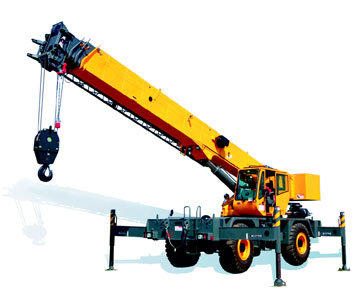 |
The superstructures of rough-terrain cranes are fully rotating, and always support the boom. On some rough-terrain cranes, the cab is also located on the superstructure. On other rough-terrain cranes, the cab is mounted on the truck chassis. Rough-terrain cranes use telescoping booms. These booms are also used on truck cranes, and are described in Subsection G601.03. Telescoping booms on rough-terrain cranes are typically smaller than those on a truck crane, which reflects the smaller overall size of the rough terrain crane.
6. Over head or Gantry Cranes
These cranes are generally used involving large span service areas and are free from floor obstructions. They are widely used in erection, foundry, steel plants, storage yards and different types of industrial works. These type of cranes consist of two main parts i.e., the bridge and the crab. The bridge consists of two main girders fixed at their end to end and capable of moving on gantry rails. The crab consists of the hoisting gear mounted on a frame. The frame itself is mounted on another set of wheels and capable of travelling across the main girder.
7. Tower Cranes
Tower crane is the only type of crane specially designed for buildings and other high rise structures. They can distribute material for whole plan area of a tall structure. Tower cranes can be fitted with a derricking jib or horizontal jib with traversing trolley. A derricking jib is necessary if required to be raised to clear obstructions. A horizontal jib is easier to operate, is faster and has lower power consumption.
Tower cranes can be rail mounted but require properly laid level track; the travel is also electrically operated. Other options include fixed base tower crane or climbing tower cranes when attached in the height to be frame work of the building. In such cases the designer of the building should permit attachment with resultant loads, at appropriate points. With winches of higher capacity, the maximum height of the attached crane can be increased.
Site conditions regulate the height of the unattached crane depending upon exposure to high winds etc. The fixed base may involve substantial area and depth of concrete. Cabins are usually on top of the mast and jib slews either with the mast or around the mast. Control is usually by the operator; remote control is also possible. The cranes are usually electrically operated.
All tower cranes consist of the same basic parts:
- The Base bolted to a large concrete pad that supports the crane.
- The Mast (or tower), which gives the tower crane its height.
- Attached to the top of the mast is the Slewing Unit (large ring-gear and motor) that allows the crane to rotate.
- Attached to the slewing unit is the Jib (or boom), the machinery arm, the counterweights and,
- The Operators Cab.
The long horizontal jib (or working arm), is the portion of the crane that carries the load and a trolley runs along the jib to move the load in and out from the crane centre. The shorter horizontal machinery arm contains the crane's motors and other electronic devices as well as the large concrete counterweights.
The mast is normally available in sections (usually 3 to 6 meters) to facilitate easy and convenient handling during erection and dismantling. Mast sections are connected by pin or bolted joints. Special torque wrenches are required in the case of bolted joints and are usually supplied along with the crane.
Tower cranes feature a high manoeuvrability, a large space below the crane and high arrangement of the boom which can pass over the erected structures.
The type and number of cranes to be used will depend on the plan, size and shape and the height of the building and the access spaces around it. Where the tower crane is located outside a high rise structure, it is often have to be tied to the structure at intervals to stabilize the mast. The structure assists in taking up the reaction at a certain points, in which case the structure has to be designed for the stresses generated by the anchors.
Mobile tower cranes are subdivided with respect to their running year into rail mounted, truck, wheeled and crawler cranes. Most widely are rail mounted cranes, they are simple in service and ensure a high safety.
Where access around the site is restricted, a tower cranes might be used internally by leaving out the floor panels or making use of the lift shaft or stair well. Thus it is possible to operate from a more central point in the structure and make most use of its reach. Alternatively, a climbing crane may be more economical. A disadvantage when the lift shaft is used is that the lift installation is delayed pending removal of the crane. However, it is possible to construct the lift lining and assemble from the bottom up, following the passage of the crane.
8. Conveyors
A conveyor system is a common piece of mechanical handling equipment that moves materials from one location to another. Conveyors are especially useful in applications involving the transportation of heavy or bulky materials. Conveyor systems allow quick and efficient transportation for a wide variety of materials, which make them very popular in the material handling and packaging industries.
9. Fork Lifts
A forklift is a powered industrial mini truck used to lift and transport materials. Forklifts are available in many variations and load capacities. In a typical warehouse setting most forklifts used have load capacities between one to five tons. Larger machines, up to 50 tons lift capacity are used for lifting heavier loads are also available in the market.
10. Construction Lifts
Construction Lifts are also referred as Hoists. These can be used for transporting the workers and also materials. Also known as a Man-Lift, temporary elevator, builder hoist, passenger hoist or construction elevator, this type of hoist is commonly used on large scale construction projects, such as high-rise buildings or major hospitals. There are many other uses for the construction elevator.
Many other industries use these Hoists for full time operations. The purpose is being to carry personnel, materials, and equipment quickly between the ground and higher floors, or between floors in the middle of a structure.
PILE DRIVING EQUIPMENT
A pile is a structural member that is driven into the ground to provide support for a structure. Piles are made from timber, concrete, or steel, and come in a variety of shapes and sizes. They can be driven into the ground vertically or at an angle. The material, size, and angle of the piles used on a Project are determined during the design phase. These characteristics will impact the type of pile driving equipment that the Contractor uses.
The ground material the piles are driven into also impacts the choice of pile driving equipment. Piles can be driven through gravel, sand, or fine-grained soils with a range of moisture contents. During driving, friction will build up between the ground material and the pile. The amount of friction expected, as well as the material present, will play a role in determining the best type of pile driving equipment.
A kind of ground treatment for strengthening the ground soil and makes it capable of supporting the load of building is called piling. It involves the driving of pile into ground below the ground level. Generally, concrete piles, timber piles, steel piles and bored piles are used to make the soil stronger for holding the weight of a building. On the other hand, sheet piles act as supporting wall due to ability of sustaining the lateral load. Specially designed piling equipment can be used for driving piles into the ground.
Piles are installed by a special pile driving device known as a pile hammer. The hammer is usually suspended from the boom of a crawler crane, supported on a large frame called a pile driver or carried on a barge for construction in water. The hammer in general is guided between two parallel steel members called leads. The leads may be adjusted at various angles for driving vertical and batter piles.
There are several types of hammers that are in use and vary in size, applicability, design etc based on the type of pile that is being driven including the soil characteristics.
Drop hammer- The drop hammer in the pile driving equipment consists of a heavy ram in between the leads. The ram is lifted up to a certain height and released to drop on the pile. This type is slow and therefore not in common use. It is used in the cases where only a small number of piles are driven.
Single acting hammer- In a single acting hammer a heavy ram is lifted up by steam or compressed air but dropped by its own weight. The energy of a single acting hammer is equal to the weight of the ram times the height of fall.
Double-acting hammer- The double-acting hammer employs steam or air for lifting the ram and for accelerating the downward stroke. The energy of a double-acting hammer is equal to the (weight of the ram I mean effective pressure I the effective area of ram) 1 times the height of fall.
Diesel hammer- The diesel hammer is a small, light weight and highly mobile. They use gasoline for fuel. To start the operation, the ram is raised, and the fuel is injected. As the ram is released, the ram falls and compresses air and fuel. The air and fuel becomes hot because of the compression and the air-fuel mixture is ignited. The resulting explosion Advances the pile and Lifts the ram. If the pile advance is very great as in soft soils, the ram is not lifted by the explosion sufficiently to ignite the air-fuel mixture on the next cycic, requiring that the ram be again manually lifted.
Vibratory hammer- The principle of the vibratory driver is two counter-rotating eccentric weights. The driving unit vibrates at high frequency and provides two vertical impulses, one up and one down. The downward pulse acts with the pile weight to increase the apparent gravity force. These hummers have reduced driving vibrations, reduced noise, and great speed of penetration.
HOISTING EQUIPMENTS
Hoisting is a process of lifting a weight from one location and moving it to another location which is at a reasonable distance. Big projects such as, construction of dams, industrial buildings etc. require extensive use of hoisting equipment. Hoisting equipment includes jacks, winches, chain hoists and cranes.
These equipments are used for lifting the loads, holding them in suspension during transfer from one place to other and placing them at designated location. Some of the commonly used equipments are;
- Pulleys
- Chain hoists
- Winches
- Cranes
CONCRETE EQUIPMENT
The role of concrete equipment plays a very vital role in the construction industry and they vary from simple 10/7 mixers to complicated, computerized batching plants. Concrete production involves batching, mixing, handling and transportation, placing, finishing curing as per the desired specifications.
1. Hand fed tilting mixers
These are the smaller capacity mixers. Aggregate, cement and water are fed into the drum by hand. The revolving drum with its mixing blades gives a lifting, combing and agitation to mix the concrete.
2. Loader fed tilting drum mixer
These mixers are of larger capacity as compared to the fed tilting drum mixers. Mixer is fitted with a loading hopper operated by rope. Mixing drum is supported on solid iron yoke and can tilt either side.
3. Reversing Drum mixers
These are used in larger work. This machine comprises of two sets of blades, one blade mixes while drum is rotated while the other discharges the mix when drum is rotated in reverse.
4. Roller Pan Mixer
These are used for mortar mixing in general. The roller and mixing blades rotate in a pan and not only mix the material but also produce a kneading and crushing action. The drive to the rollers and mixing blade is provided by either diesel engine or electric motor.
5. Transit Mixers
Concrete mixed is transported from the batching and mixing plant to site. Fully or partly mixed concrete is transported through truck mixers, when the construction site is far from batching plant. Entire mixing is carried in journey. Addition of admixtures helps concrete not to set due to delays in transportation. However, concrete thus mixed and carried should be used within 3 hrs preferably.
6. Concrete dumpers
Concrete Dumpers are used to carry mix from concrete mixer to site. Mixer is kept near the site from the concrete dumpers. These are used for short leads only. This Dumper may be two wheel or four wheel drive propelled by diesel engine has a low centre of gravity.
7. Concrete Pumps
Concrete Placement Speed is always an important factor and one of the benefits of using concrete pumping is that it helps to place the concrete more accurately without involving much of a labour. Since the cohesive nature of the concrete mix is one of the necessities for mixing, we are assured of a good concrete. In case of high rise buildings, multi-stage pumps are also used. There are many projects where the concrete pump is directly placed below the batching plant and the concrete pipe line is connected to the location of pour. Capacities of these pumps vary in terms of their delivery. Depending on the way the concrete is transported, concrete pumps are classified in two basic types; the boom pump and the line pump.
The boom pump uses a remote controlled robotic arm to place concrete where it needs to go, and they’re often used in large construction projects. Boom pumps are able to pump concrete at high volumes and are extremely accurate, which is why they are used for larger projects.
Placer Booms
Placer Booms are self-contained units consisting of a truck and frame, and the pump itself. These are used for concrete pours for everything from slabs and medium high-rise buildings, to large volume commercial and industrial projects. They range from single-axle truck mounted pumps used for their high maneuverability, suitability for confined areas, and cost/performance value, to huge, six-axle rigs used for their powerful pumps and long reach on high-rise and other large-scale projects.
Booms for these trucks can come in configurations of three and four sections, with a low unfolding height of about 16 feet. This low unfolding height is ideal for placing concrete in confined areas. Longer, five-part booms can reach up or out more than 200 feet.
Because of their reach, boom trucks often remain in the same place for an entire pour. This allows ready mix trucks to discharge their loads directly into the pumps hopper at one central location and helps to create a more efficient jobsite traffic flow.
These pumps require steel or rubber concrete placing hoses to be manually attached to the outlet of the machine. Those hoses are linked together and lead to wherever the concrete needs to be placed. Line pumps normally pump concrete at lower volumes than boom pumps. The capacity of the pump varies from model to model and depends on the volume of concrete it delivers at the end point per hour.
8. Batching Plants
A concrete batching plant is special form of machinery designed to homogeneously mix various ingredients for formation of the right concrete mixture that can be used in various applications. Types of Concrete Batching Plants Depending on the how the concrete in mixed and when the concrete reaches the construction site, the concrete plants are mainly classified into two categories – ready mix concrete plant and central mix concrete batching plant.
In a ready mix concrete plant, dry form of concrete excluding water is mixed thoroughly. This dry concrete is then transported in a concrete transport truck to the construction site. Water is added to this dry concrete mixture when the truck is on its way to the job site.
The another popular form of concrete batching plant is a central mix concrete plant in which either all or only a few ingredients of concrete are mixed along with water at a fundamental location where the plant is situated. This mixed concrete solution is then disposed to the job site for construction purposes. This is usually a high capacity batching plant, which generally consists of silos, bins, concrete batchers, conveyors and control equipment. They are stationary mixer units as compared to the mobile batching plants which consist of frameworks carrying batchers, conveyors, scales, control equipment, small silos and are normally adapted to be transported from site to site.
9. Vibrator- For compacting the concrete after its placement concrete vibrator is used. It help volume of concrete quickly placed, give high density, reduce air voids. Types of Vibrators;
- Internal vibrators-Use on large work for flat slab.
- External or form vibrators-uses for thin section of walls.
- Surface vibrator-used to finish concrete surface such as bridge floor, road slab, section platform.
- Table Vibrator-used for consolidation of precast units.
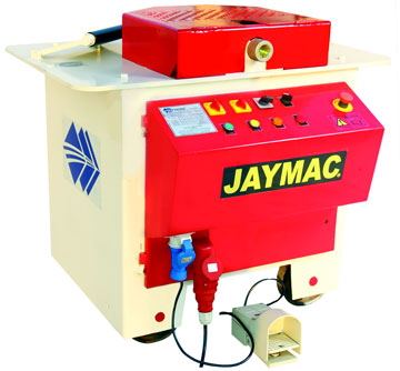
Bar Bending and Shearing Machines
The cutting and bending of steel is one of the most important activities in any kind of construction or infrastructure projects. This could be done on site manually or mechanically. In the traditional method of cutting and bending, there is a possibility of inaccuracies creeping in. This is avoided by using Cutting and Bending machines. Reinforcement bars of various diameters (ranging from 6 mm to 40 mm) are cut and bent as per the bar bending schedule. We find bending and cutting machines separately in the market while there are also machine performing dual duties. The machine usually consists of electrical panel board, limit switch, emergency stop and indicator. Different dies are provided for different sizes of bar. Skilled and trained operators are needed to operate these machines.
 |
Plaster sprayers enable us to apply plaster up to five times faster than traditional methods and can reach 80 meters height. Most of the plaster spray machines prefer ready mix plaster. Plastering Machine is particularly designed for the building and construction industry to improve work efficiency and effectiveness. Below are the advantages of using plastering machine:
- Better quality plastering.
- Eliminates leakage, cracking and peeling off dried plaster.
- Helps in reducing manpower.
- Faster.
- Low maintenance & low downtime
These spray machines can also be used for internal plastering with gypsum based mix in which case regular washing of the equipment is required.
Auto Rendering Machines
Rebar Tying Tool
These are normally rechargeable - battery operated hand held tools used for tying the rebars. They are capable of making one tie per second and very effective with 16 gauge GI binding wire.
Plaster Spray Machines
Auto rendering machine provides high quality wall rendering. Machine can achieve mortar coating and smoothing in the same time. When effectively used, it can deliver up to 500 sqm per day of plastered surface. Some of the salient features of Automatic Rendering Machine are; It can reach the very top of the roof - Combine with the screw and conveying belt to achieve the vibrating compaction - Fast positioning - Hydraulic lifting methods to improve the stability of the machine- If the cable fall off, the machine will stop automatically - Larger hopper, more materials can be loaded.
Power Trowel
A power trowel, also known as a "power float", "helicopter" or "trowel machine", is used to obtain a smooth, uniform, flat surface doing away with manual inaccuracies. Power trowels can be generally classified based on the way they are controlled.
- Ride - on power trowels are operated by an operator seated on the machinery and controlling power trowel movement.
- Walk-behind power trowels are used by an operator walking behind the machine.
It is mandatory to level and compact the concrete surface prior to the use of Power Trowel. It is also essential to trowel at the correct time. The operator must wait until the soft concrete hardens sufficiently to take the weight of the machine and the operator.
The trowel is fitted with either float blades or floating disc at the time of Floating, which is the first pass. The operation during the floating pass should be slow and uniform. This is then followed by the second pass to remove any marks due to disc movement. Once the surface has been 'floated', the blades of the trowel are changed to finishing blades. The finish pass should be started when the surface has dried off, and walking on the surface leaves no appreciable indentations.
For the finishing pass the blades are angled to suit the concrete, increasing the angle after each pass - an angle of around 5-10º is usual, the steeper the angle the harder the finish. Several passes with the finish blades may be required to achieve the specified finish.
Conclusion
There are several other construction equipments used in the construction industry that are beneficial and help us in achieving optimum performance. The choice of using suitable machinery depends upon the awareness of availability of such machines in the market. Several tools like concrete chippers, hacking tools, grove cutting machines, shotcrete equipment, grouting pumps, wagon drilling equipment, Dewatering pumps etc to be considered while planning a fast track project.
References
1. Earthwork Equipment Manual
2. Presentations by Prof.dr.Nerman Rustempasic and Ahmed El Sayed
3. Presentations by Dr.U.J.Kahalekar
4. Presentations by Ashish parihar, Hunsraj bhalekar
5. Construction Industry in 2013-11-07
6. Benifits of concrete pumping presentation.
7. Construction Equipment Guidelines by IBEF