CASE STUDY - 2
Partially Constructed PSC Bridge Connecting Road From Gulbarga To Humnabad
Introduction
PSC Bridge under construction is located in the backwaters area of the reservoir dam which is about 11 kms from the bridge. It is along the national highway no. 218 connecting Gulbarga and Humnabad. It consists of 7 spans of 30.2m each comprising of 4 PSC girders on each span totaling 28 girders with deck slab and approaches. The overall length of the bridge is 210m. The foundation consists of open foundation and well foundation depending upon the location of the piers and abutments. Details are given in Fig - 2.1. A panoramic view of the site is shown in Fig - 2.
In the AL-P1 span the G2 girder had been successfully prestressed. However, the GI girder during post tensioning hogged in the form of a bow, got cut into two pieces at mid span and miserably collapsed onto the supporting centering. The entire work was stopped immediately and ordered for an enquiry for the collapse.
The salient features of the bridge during the visit are as follows:
| Location |
Across Bennethora river, on National Highway No.218 between Gulbarga and Humnabad.
|
| Type of bridge |
PSC deck girders (4 Nos.) of overall depth 1500mm supported on R C piers and Abutments rested on open / well foundations. |
| Number of spans |
Seven spans of 30.20m each. |
| Total Length of Bridge |
210 m |
| Grade of concrete |
Abutment, Pier, Pier cap, Well, Well cap and Steining - M30PSC deck girders - M40 |
| Grade of steel |
Fe-415 |
| Strands |
Nominal ultimate stress 19000kg/cm2 |
| Contract Period |
17 months |
| Construction work stopped |
August 2010 |
| Construction status at the time of investigation |
Abutments Right n Left - Completed
Pier-P1 - Completed
Pier-P2 - Completed
Pier-P3 - Completed
Pier-P4 - Completed
Pier-P5 - Well foundation partially completed
Pier-P6 - yet to be started
|
| Deck Girders - span 1 |
Girder G1 & G4 reinforcement fabrication partially completed.
Girder G2 prestressing completed.
Girder G3 only concreting completed.
Girder G1 & G2 only centering completed
|
Fig.2.1. DETAILS OF PSC
Fig - 2.2 : Panoramic View of PSC Bridge under Construction
Physical Investigation
A detailed physical inspection was made and it was observed that the construction works are at different levels as presented (Fig - 2.2 and 2.3).
-
Overall construction work had come to a standstill (Fig - 2.2 and 2.3)
-
PSC Girder G1 was possessing central cracks due to failure by post tensioning and was resting on centering below (Fig - 2.4)
-
PSC girder G2 has been cast in place, post tensioned and grouted. But end anchorages are left open without any cover. The unprotected end anchorages have corroded considerably. (Fig - 2.3)
-
Girder G3 has hogged up to an extent of about 90-95mm due to pre-stressing.
-
At the left support of G2 girder, it has cracks from support extending upwards. Corners have got crushed and the inside honeycomb concrete is exposed. This shows that the concrete is not all that good.
-
PSC girder G3 has been cast and pretension cables are inserted in respective ducts but not pre-stressed (Fig - 2.3)
-
PSC girder G4 reinforcement cage is ready, partially shuttering is done and not concreted (Fig - 2.3)
-
Piers P1 and P2 are completed including pier cap (Fig - 2.2).
-
Piers P3 and P4 are completed including pier cap (Fig - 2.2)
-
Approach and exit abutments are completed. But concreting is of poor quality.
-
Pier P5 well sinking has been completed, but it is submerged in standing water and only reinforcement is seen above water.
-
P6 pier with foundation yet to be constructed.
-
The unused reinforcement lying on the ground exposed to atmosphere is totally corroded.
-
Bearing pads are completed on the top of few pier caps and some reinforcement fabrication ready for concreting. But the reinforcement exposed are corroded.
-
As the construction work has totally stopped, engineering records like quality control, sequence of working etc., were not available at site.
-
The centering and scaffolding provided for the PSC girder are unprotected. If anybody moving around the place removes any of the centering due to some reason or the other, it will be a total collapse of the existing girders which may lead to further problems (Fig -2.4a)
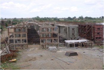 |
Fig - 2.3 : Four Girders in the First Span AL - P1
Details of Failure PSC Girder G1
Figure 2.4 shows clearly the failure mode of PSC Girder. A closeup view of the girder indicates that the quality of concrete is questionable.
The probable sequence of failure of the PSC girder is indicated in the Fig - 2.4. When the maximum permissible prestressing force was reached, the girder would have got hogged upwards. The magnitude of hogging deflection was so high that the elongation in the HT cables exceeded maximum permissible value and have got cut, releasing the entire prestressing force. At this stage the maximum tensile stress would have definitely crossed in ultimate value and hence concrete has also failed.
At this stage the PSC girder with zero prestressing force had become an ordinary RCC girder which could not withstand its own self weight and has fallen flat onto the centering below.
The magnitude of the impact due to sudden fall was so high that the vertical stirrups in the girder have buckled as if it is subjected to severe earthquake (Fig 2.5).
a) Girder Failed during Post Tensioning
Fig - 2.4 : Girder - G1 as on June 16, 2010
b) Close-up of Failed Sections c) Close-up of Cracked Section
a) Crippled Reinforcement b) Buckled Reinforcement
c) Spalled Concrete showing Weak Honeycomb Concrete d) High Tension Steel with Pre-tension Released after Failure
Fig - 2.5 : Few More Views of Failed Girder - G1
Why should PSC Girder Fail
The other girder G2 had already been post tensioned successfully earlier and it is lying next to it in the middle of the breadth of span. This girder G1 which is similar to the girder G2 in all respects failed. The question now is why G1 failed when G2 is intact.
Probable Reasons for the Failure of PSC Girder G1
The girder G1 would have failed due to any one or combination of the following factors.
-
Errors in structural designs
-
Misalignment of HT cables
-
Excessive prestressing force
-
Excessive elongation of HT cables
-
Erroneous pressure gauge of prestressing jack
-
Calibration of pressure gauge questionable
-
Quality of concrete and concreting
-
Compressive strength of hardened concrete was much less than the designed strength
To ascertain the above factors detailed investigation was done one after another.
Proof Checking of Structural Designs
The following documents were provided for proof checking of the structural designs of the PSC Bridge.
| Drg. No. U3/60/BEN/01 (ALT)- Rev A |
General arrangement drawing at Ch.20.119 `(Alternative)
|
| Drg. No. U3/60/BEN 01/05 |
Cable layout details of PSC girder at Ch. 20.119 |
| Drg. No. U3/60/BEN-01/06 |
Reinforcement details of longitudinal girder at Ch. 20.119 |
| Drg. No. U/GEN/UPG - 01 |
General Notes |
STAAD Modelling
Using the data given in the INPUT FILE in the detailed design calculation document provided, an independent computer analysis was made using the standard software package STAAD-PRO-2007, creating separate 3D model.
It was observed that the design values of maximum bending moment and shear force considered matched with the present analysis values.
The maximum deflection was well within the permissible values.
Design of Post-tensioned Beam Outer Girders
Provisions of design requirement as per IRC : 18-2000 have been followed throughout the designs.
| Grade of concrete |
M40 |
| Grade of reinforcement steel |
Fe 415 |
| Yield strength of prestressing cable |
1900 N/mm2 |
Four numbers of prestressing cables have been provided (Fig - 2.5d) as per the design requirements which are in order.
The design stresses in concrete and pre-stressing steel are well within the permissible limits as per the relevant codes of practice.
All the losses due to prestress are considered as per codal requirements.
Final mid span deflections due to self weight, live load and prestress are within the permissible limits.
Cable layout details as per design and as per details provided in the Drg. No. U3/60/BEN-01/05 are presented in the Table - 2.1.
Table - 2.1 : Comparative Statement of Cable Profile
Inferences on Proof Checking
Based on the independent structural analysis and design of PSC Bridge, made as per relevant IRC Codes of Practice and after comparing with original designs made by the Consultants, it was observed that the structural designs and the relevant structural drawings provided are in order.
Non Destructive Testing of RC Structural Elements
Non Destructive Tests were conducted by a reputed agency accredited by NABL, to assess the existing strength of hardened concrete and the quality of construction. The following investigative studies were carried out:
-
Semi-Destructive test (core test).
-
Non-Destructive tests to assess the quality / homogeneity of in-situ concrete :
-
Ultrasonic Pulse Velocity Test
-
Rebound Hammer Test.
-
Covermeter studies to assess the thickness of cover concrete provided.
Core Testing
To assess the compressive strength of concrete as per IS: 516, concrete cores of dia 90mm were taken spaced at 2m c/c over the entire length of the failed girder and cores were tested in the laboratory.
An abstract of NDT and Core test results is given in Table - 2.2
Design compressive strength of concrete : 40 N/mm2
Table - 2.2 : Abstract of NDT and Core Test Results
Quality of Existing Concrete in Failed Girder G1
From the photographs presented in Fig - 2.4 and 2.5, it is clearly seen that the concrete is honey combed. The disintegrated concrete around the central crack clearly indicates that the concrete is not well compacted and there is no bond between concrete and reinforcement steel.
Inferences from Test Results
Quality/strength of concrete in the failed PSC Girder G1 is non-uniform and does not conform to M40 grade concrete. The existing strength is less than M25. Hence, it was not fit for prestressing / post tensioning as per IS : 1343 and IRS Codes of Practice.
Reasons for Failure
Based on the results of proof checking of structural designs of PSC girders and NDT and core test results it is confirmed that the failure of PSC girder during post tensioning is mainly due to poor quality of concrete and construction.
a) Group of Girders after Dismantling G1
b) Debirs of Dismantled Concrete of Girder G1
Fig - 2.6 : Dismantled Concrete of PSC Girder - G1 after Failure
Final Recommendations
-
The detailed design calculations submitted for main PSC girders, were critically scrutinized independently as per relevant IRC Codes of Practice and other relevant IS Codes and were found to be in order.
-
It was recommended to dismantle the failed PSC girder G1 immediately (Fig - 2.6 ).
-
In the present site condition, in situ casting of PSC girders shall not be carried out.
-
It is strongly recommended to adopt Precast Post Tensioned PSC girders in the new construction.
-
The existing girders G2 and G3 having variable strength and are not dependable, from durability consideration, shall be dismantled totally.