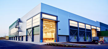
Pre Engineered Metal Buildings
Components & Processes
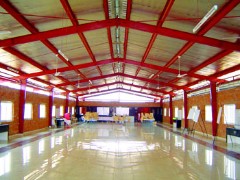
Primary Frame
Comprising of Columns and Rafters-the PEMB rigid frame comprises tapered/straight columns and tapered rafters (steel plate fabricated 'I' or 'H' sections are referred to as built-up members). The frame is erected by bolting the end plates of connecting sections together.
Primary frames provide the vertical support for the whole building plus providing the lateral stability for the building in its direction while lateral stability in the other direction is usually achieved by a bracing system. The width of the building is defined as the out-to-out dimensions of girts/eave struts and these extents define the side wall steel lines. Eave height is the height measured from bottom of the column base plate to top of the eave strut. Rigid frame members are tapered using built-up sections following the shape of the bending moment diagram. Columns with fixed base are straight. Also the interior columns are always maintained straight.
Main frame orientation
Building should be oriented in such a way that the length is greater than the width. This will result in more number of lighter frames rather than less number of heavy frames, this also will reduce the wind bracing forces results in lighter bracing systems.
Main frame types
There are several types of main frames used in PEB buildings; the choice of the type of main frame to be used is dependent on:
- Total width of the building.
- The permitted spacing between columns in the transversal direction according to customer requirements and the function of the building.
- The existence of sub structure (RC or masonry)
- The architectural requirements of the customer specially the shape of the gable.
- The type of rain drainage (internal drainage availability).
- Any customer special requirements.
Secondary Frame
Comprising of Purlins, Girts and Eave struts- Purlins, Girts and Eave struts are also known as secondary cold-formed members. There is no welding involved in their preparation. They are prepared by press bending the HR steel coil giving it the desired shape (Z- or C-shape).
 |
These are cold roll formed sections of varying thickness from 1.6mm to 3.0 mm made of high grade steel of 245 to 345 MPa. They are normally factory painted with standard red oxide or Zinc Chromate primer with holes punched as per the design requirements. |
Roofing
Upon completion of all secondary framing in the braced bay, installation of Roofing may commence and be worked in conjunction with the completion of the balance of the secondary framing to speed up the process. The Structure without sheeting should not be left standing for prolonged periods of time without taking proper precautions (temporary bracing, Blocking etc.) to prevent wind damage especially to purlins and girts due to excessive vibration they expose to in the no sheeted condition.
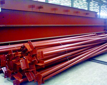
The entire primary framing members and secondary structural members are pre-sheared, pre-punched, pre-drilled, pre-welded and pre-formed in the factories before shipping to site for erection are shown in Fig: 3. Quality of building part is assured as buildings are manufactured completely in the factory under controlled conditions. At the job site, the pre-fabricated components are then fixed and jointed with bolt connections. Saving of material on low stress area of the primary framing members makes Pre-engineered Buildings more economical than conventional steel buildings especially for low rise buildings spanning up to 60.0 meters with eave heights up to 30.0 meters. Furthermore, Pre-engineered Building system focuses on using pre-designed connections and pre-determined material stock to design and fabricate the building structures, thus significantly reduces the time for design, fabrication and installation.
Gable End Framing
These are end wall frames classified under main frames.
Wind Bracing System
This System provides longitudinal stability for the building. It consists of steel cross bracing located in the roof and side walls in one or more bays depending on the loadings and the length of the building.
Roof and Wall Sheeting
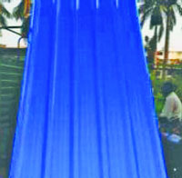 |
Plain or colour coated steel sheets profiled as per standard configuration are used for roof and wall sheeting. The steel sheets are generally made from Zinc-alume or Galvalume with varying thicknesses ranging from 0.47mm to 0.55mm. In some special cases, thickness up to 0.8mm can also be got manufactured. These profile steel sheets are usually categorized into two types namely Through Fastened and Standing Seam depending upon the type of fixing arrangement followed.
|
Prefab Panels and Insulation
Colour coated profiled or ribbed steel sheets are used normally for roofs and wall cladding in combination with insulation panels. Minimum thickness of sheeting used is 0.5mm made of high tensile steel. Manufacturers and suppliers of these materials will have their own fixing details prescribed along with the consignment supplied. The siding walls can also be insulated by providing a double skin profile or ribbed steel sheet or cement board sheets on inner side wall cladding having Rockwool Insulation slab sandwiched in between and held in position with the help of 'Z' spacers in between the two steel sheets. In similar pattern a double skin insulated roofing system can also be erected. The cement boards will give a conventional white finish after painting. In case of roofing, insulation panels are fixed underneath the roofing sheets which are subsequently provided with false Ceiling of suitable system.
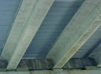
Metal Decking and Mezzanine
| Standard mezzanine structure consists of built-up beams that support built-up, hot-rolled or cold-formed mezzanine joists which in-turn support a decking sheet, commonly known as metal deck. While Metal Decking remains in place and acts as slab shuttering, and concrete slab can be cast with reinforcement. These mezzanines are used for office space, storage or equipment supports in industries. |
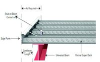 |
| If the loading on the floor is not heavy then, 50mm thick MDF boards, Panels are also used as underlay. Some of the benefits of Metal Decking sheets are enumerated below. |
Fixing of Deck Sheet |
Versatility (Can also be used as roofing and cladding)
- Reduces slab thickness (Concrete)
- High Strength to Weight Ratio
- All weather conditions
- Uniform Quality Durability
- Economy and value
- Acts as Composite member & Permanent shuttering
- No major reinforcement required
- Can be used as working platform during construction
- Speedy construction
|
Cranes and Lifting Hoists
As per Indian Standard Specifications 807:2006 and 3177:1999 Cranes have basically divided into four Classes;
- Light Duty: These are normal maintenance cranes which are not in constant use. Cranes for periodical maintenance of plant and machinery come under this category. These types of cranes have rated life not less than 20 year of 250 days per year and hour working time per day. Their speed is slow and the structures are light.
- Medium Duty: This class perhaps covers the largest number of cranes used in the industry. These types of cranes have rated life not less than 20 years of 300 days per year and 1 ½ hour working time per day.
- Heavy Duty: For Workshops and Production shops, where the cranes, in addition to normal handling work, also become a part of production process. These types of cranes have highest usage is in steel industry important storage and in some other selected industries. These are for continuous duty operation. These types of cranes have rated life not less than 20 years of 333 days per year and 6 hour working time per day.
PEBs can be equipped with one or different types of cranes namely, Overhead EOT cranes, Semi-gantry cranes, wall mounted cranes, Mono rails and Under Slung cranes for various material and equipment handling operations inside. These buildings are being designed for crane capacities ranging from 1MT to 250MT. The Gantry Girders which are nothing but crane runway beams are built-up sections with platforms, catwalks and ladders for maintenance purpose.
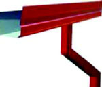
Accessories
 |
 |
| Down Takes |
Turbo Ventilators |
 |
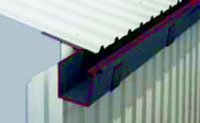 |
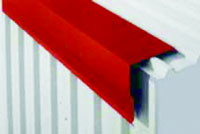
| Ridge Cap |
Gutter |
 |
 |
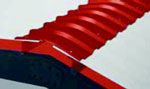
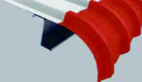
| Curved Eave |
Corner Trim |
Pre-engineered Buildings can be fitted with different structural accessories including mezzanine floors, crane runway beams, roof platform, catwalk and aesthetic features such as canopies, fascia's, interior partitions etc. The buildings are made water proof by use of standing seam roof system, roof drainage components and trims. This is a very versatile building system and can be furnished internally to serve any functions, and accessorized externally to achieve unique and aesthetically pleasing architecture designs, making it ideal for application such as factories, warehouses, workshops, showrooms, supermarket etc.
As per the functional and architectural requirements, accessories are supplied in ready to fit condition. Ventilation and lighting systems should be properly designed in consultation with an expert. In addition to frame, wall, and roof systems, there are other components of a metal building system generally referred to as accessories. These include roof vents, light transmitting panels, interior liner panels, louvers, wall lights, wall openings, windows, pedestrian doors, overhead doors, fascias, mansards, canopies, and trim in general. Any numbers of these items are required to complete a metal building system. These individual components are also manufactured as integral units for the metal building system. When installed, they will be compatible in both design and appearance with the wall and roof systems that they penetrate.
Modular Doors, Windows
Steel or aluminium framed doors and windows are fixed to the purlins or the supporting profiled steel either by welding or bolted to the flanges already fixed to the purlins. Proper flashings are applied wherever necessary.
Finishes
Finishes including Floors, Paints, Services and False Ceilings can be achieved as per the design requirements and aesthetic parameters. Under normal circumstances, inside flooring can be of concrete, epoxy or any other heavy duty flooring. Special care is to be taken in those areas where they are sunk to carry water and sanitary pipes.
PEMB Processes
Pre-engineered buildings (PEB) steel parts are required to be installed in a specific order due to structural safety requirements and to the logical sequence of erection. Key materials brought in during each phase of the steel construction process are briefly described in order to model the existing steel construction processes. Then the whole steel construction processes of fabrication, shipping and erection are presented.
During the construction phase of a project it is essential that the information flow is smooth and continuous throughout the process. The construction industry is dynamic by nature and requires that all parties are informed of activities that can ultimately affect the cost, schedule or quality.
Important Features of PEMB
- Pre Engineered Building System is computer assisted and designed to create a building for a specific use.
- The complete building system is Pre Engineered to facilitate easy production & assembly on site.
- In PEB System a superior corrosion protection of a thin coating of resin applied on the top of the Aluminium Zinc coating make Galvalume sheet.
- Galvalume steel is a steel sheet product with a highly corrosion resistance steel, aluminium zinc alloy hard dip coating.
- A clear organic acrylic resin coating is then applied & then thermally cured.
- A colour coating is given on the top surface for a bright appearance with a colour of the customer's choice.
Pre-Planning and Fabrication
At an early stage, general contractor and steel supplier work together to discuss project site constraints. They also determine the steel erection sequence, which represents the order in which a zone or section of the structural steel frame is delivered and erected to improve the efficiency of loading, delivery, unloading, and erection. Based on the requirement of the general contractor master schedule, and the fabricator load schedule, the steel factory creates the fabrication and shipping schedule. PEB elements where PEB parts are being fabricated are numbered and labelled on the steel members.
Labelling of PEB Elements
Transportation
Due to space inadequacy, fabricated PEB elements cannot be immediately transported to the construction site, but they are stored in the storage yard according to erection sequence. Upon delivery to the jobsite, receiving and unloading of materials should take place as near as possible to the place of erection. The lay-down area should be clean and levelled. A suitable capacity forklift for unloading and loading at erection site is desirable. Once the material arrives at site, It involves organizing the elements to match the erection procedure.
Guidelines for PEMB Design
- All Designs Shall Be As Per MBMA [Metal Building Manufacturer Association] &Client Specifies As Per IS Code.
- Live load as Per American Code = 0.57 KN/M2 and as Per IS Code = 0.75 KN/M2. (Reduction in live load to be incorporated for buildings having higher slopes)
- As Per American Code: Horizontal Deflection = L/180 & Vertical Deflection = eh/100 For Main Frames.
- Wind terrain category 3 is to be selected unless more data is available.
- In American Design, Wind Coefficients To Be Followed As Given In MBMA.
- In IS Design, Internal & External Building Wind Coefficients As Per IS -875 (Part-3).
- Generally Buildings Are To Be Designed As Pinned Except For Building Span >30m Or Crane Capacity Of More Than 5 Tons Or Height Greater Than 9 M
- Standard Purlin Laps Should Be 385 mm
Issues of Concern
Although great advances have been made in lighter and more economical fire protection systems but fire protection remains an issue of greater concern for steel structures than compared to concrete or other construction materials. The smaller members and thermal mass associated with steel structures makes it more vulnerable. The memories of collapse of world trade centre towers in USA due to fire caused by burning of aviation fuel and sudden rise of temperature leading to complete destruction of structure might not have faded away. Fire protection adds up to larger part of structural cost. It would be a challenge to engineers toward reducing these costs, while assuring adequate resistance to elevated temperatures expected during a fire.
- Buckling
Buckling and stability become more critical in Steel structures due to smaller members and large stress levels.
- Micro Cracks
The increasing yield stress, operating stress levels, emphasis on plastic and ultimate capacity, and use of welded construction have resulted in increased frequency of initiation of micro cracks and cause of fracture in bridges and industrial structures. Further development of Micro Cracks and crack growth become a major concern in areas of seismically vulnerable areas.
- Corrosion
Steel has great tendency to corrode when exposed to the environment, which leads to deterioration, increased maintenance costs, and increased reconstruction costs. Although Galvanization, paint, and coatings may provide protection against corrosion, yet they increase the overall fabrication costs of the steel structure appreciably. In hot and humid regions and industrially polluted severe environments problem is more pronounced. Therefore, engineers have to continually seek economically viable solutions to aim at reducing these costs.
- Welding
Presently welded constructions are more commonly used, for these provide stiffer, stronger structures with reduced building weight. Increased steel yield strength requires new innovative welding
| methods, because high strength steels pose more difficulty to weld without affecting adversely the ductility and performance of the structural system. Recently the use of fully automatic and semi-automatic submerged arc welding results in increase in welding speed apart from the good quality. The elimination of any fumes, smoke or any visible arc column gives an |
 |
ease of operation and efficiency; better quality &thus encourages its application in welding industry.
- Ductility from seismic considerations
Seismic design is today a must requirement for almost all civil engineering structures. Although steel is an ideally more suited material from point of view of seismic design because of its property inherent material strength, stiffness, and ductility. Weldability may affect the seismic performance and it follows that new methods to improve inelastic seismic performance of steel structures need to be investigated.
Design Cycle
The design cycle consists of the following steps:
- Set up section sizes and brace locations based on the geometry and loading specified for the frame design.
- Calculate moment, shear, and axial force at each analysis point for each load combination.
- Compute allowable shear, allowable axial and allowable bending stress in compression and tension at each analysis point.
- Compute the corresponding stress ratios for shear, axial and bending based on the actual and allowable stresses and calculate the combined stress ratios.
- Design the optimum splice location and check to see whether the predicted sizes confirm to manufacturing constraints.
- Using the web optimization mode, arrive at the optimum web depths for the next cycle and update the member data file.
- At the end of all design cycles, an analysis is run to achieve flange brace optimization.
Frame Geometry
- The program has the capability to handle different types of frame geometry as follows
- Frames of different types viz. rigid frames, frames with multiple internal columns, single slope frames, lean to frames etc.
- Frames with varying spans, varying heights and varying slopes etc.
- Frames with different types of supports viz. pinned supports, fixed supports, sinking supports, supports with some degrees of freedom released.
- Unsymmetrical frames with off centric, unequal modules, varying slopes etc.
- User specified purlin and girt spacing and flange brace location.
Frame Loading
- Frame design can handle different types of loadings as described below:
- All the building dead loads due to sheeting, purlins, etc. and the self weight of the frame.
- Imposed live load on the frame with tributary reductions as well.
- Collateral load such as false ceiling, light fixtures, AC ducting loads, sprinkler systems and many other suspended loads of similar nature.
Wind loads input such as basic wind speed or basic wind pressure that will be converted to deign wind pressure as per the building code specified by the user and shall be applied to the different members of the building according to the coefficients mentioned in the codes prescribed by the user. The standard building codes like MBMA, UBC, ANSI, IS: 875 part 3 etc are used for this purpose.
Crane and non crane loading can be specified by the user and the program has the capability to handle these special loads and combine them with the other loads as required.
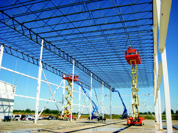
Erection Procedure
Pre Engineered Metal Building elements or the Steel framing members are normally delivered to site in pre-cut, pre fabricated sizes eliminating the in situ fabrication process to a very great extent. The elements being lighter in weight, can be easily assembled, bolted and erected in position much faster than their conventional building counterparts. If strategically planned, many activities can happen simultaneously and help in speeding up the process of completion. Once the framing is completed with roofing, interior works can be executed under shade without any time loss due to adverse climatic conditions. This section deals in brief with the erection procedure.
Foundation
Foundation design and construction together with anchor bolt planning are of paramount importance to the assembly and erection process of any Pre Engineered Building. Improper foundation construction will limit the building's performance, which may lead to costly repair(s). Strict adherence to anchor bolt planning is critical for proper seating of PEB elements and consequent dimensional accuracies.
The anchor bolt setting is the most important factor in achieving a trouble-free component alignment and fit-up. Wrong location of anchor bolts and mis-alignment are the most frequent and common errors made in Pre Engineered Metal Building construction. Some of the basic points to be considered are listed below:
- Alignment to be checked thoroughly before casting of foundation.
- Alignment of Anchor bolts, anchor depths, bolt diameter and protrusion above the surface etc to be verified.
- Top level of foundation/s ensured as per assembly drawings.
- Anchor bolts not to be disturbed when the concrete is green.
- Proper templates are provided for anchor bolts to be held firmly while casting.
- Protection tapes are wrapped around bolts and nuts before casting.
- Backfilling around the foundation is compacted, completed and leveled prior to erection.
After ensuring accuracy of foundations and anchor bolts, the erection procedure has to start with utmost care and safety considerations. Before starting erection, make sure that complete set of Erection drawings marked "Issued for Construction" are available at site.
Material Layout
Prepare a proper material layout plan following the erection sequence. Unload and store all materials in a careful, safe and orderly manner. Job sites where storage space is restricted require detailed planning.
Storage and protection
 |
Block above the ground to keep water out
Slope bundles for drainage.
Stack sheeting with spacers between bundles.
Cover with canvas tarpaulin to protect from rain.
Tie down cover ends away from the stack to permit air circulation.
Do not wrap under or restrict air movement.
It is Important not use plastic sheeting as a cover because it will promote moisture.
|
Steel Framing
- Check anchor bolt plan and erection drawings for special conditions.
- Erect Primary columns in place and tighten anchor bolt nuts.
- Attach girts and install temporary bracings.
- Check for verticality and alignment.
- Assemble roof rafter on the ground and check for accuracy as per drawings.
- Check bolted connections, primer provision, welding of elements etc.
- Erect the Rafter Beam and hold it till it is properly bolted and anchored to the columns.
- Provide temporary bracings and anchors.
- Erect the second rafter beam and hold it in position.
- Erect the Peak purlins and Eave struts. If the roof rafter consists of more than two segments, additional purlins are to be installed while roof rafter is held in place so that there are at two purlins spanning between roof rafter segments.
- Erect all the remaining Girts, Purlins and Bracings and secure the bay. Please note that until this procedure is completed, no further erection to be allowed.
- Check for plumb, diagonals and other dimensional accuracy.
- Repeat the erection procedure for other bays. Please note that, Eave struts and peak purlins may be installed in intermediate bays between braced bays to stabilize frames, however, do not start more work than can be completed in a work day to ensure all steel component framing is completed in those bays before leaving the site at the end of the day.
- Complete the erection of Main and Secondary Framing and bays as explained above.
- Provide all roof bracings, Column bracings, Wind bracings etc as per drawing to secure the framing.
Roofing
Upon completion of all secondary framing in the braced bay, installation of Roofing may commence and be worked in conjunction with the completion of the balance of the secondary framing to speed up the process. The Structure without sheeting should not be left standing for prolonged periods of time without taking proper precautions (temporary bracing, Blocking etc.) to prevent wind damage especially to purlins and girts due to excessive vibration they expose to in the no sheeted condition.
Check List
- All manufacturer drawings and design calculations shall bear the professional seal and signature of the design engineer.
- Roof system is very light and hence wind uplift requirements for roof deck, roof structural members, anchorage of steel columns and column piers/footings to be properly checked. Pay special attention to net uplift force at the columns that are part of vertical cross-bracing frames.
- Horizontal cross-bracing shall be provided on the roof plane in both directions.
- If using standing seam metal roof deck with clip anchors, place the continuous row of screw anchors at the ridge, under the ridge flashing.
- Pay special care to the flashing at valley and intersections of roof.
- Provide portal frames and/or cross-bracing at side walls to properly stabilize the building.
- Add wind columns as necessary in between the columns of pre-engineered frame. It should easily accommodate future expansion.
- Provide horizontal ties such as tie rods or hairpins to resist outward thrust at the base of rigid frame's column.
- Foundation system including column piers/footings, tie rods/hairpins and anchor bolts must be checked against the forces calculated by pre-engineered manufacturer.
- Provide and show the location of all collateral loads such as sprinklers, ventilators, exhaust fan, under hung equipment, mechanical & electrical systems and ceilings.
- Any field modifications of structural members shall be approved by pre-engineered building manufacturer and carried out under the supervision of engineer of record or a registered structural engineer.
- Specify limitation of horizontal deflection/lateral drift of the pre-engineered frames if brick veneer and/or masonry wall are part of building enclosures and are supported laterally by girts.
- Check the connection bolts for proper tightening.
Maintenance2
Frequency of maintenance is dependent upon the environmental zone in which the building is located.
|
Building Location
|
Maintenance Period
|
|
Within 5 km of the sea.
|
Every 3 months
|
|
High pollution industrial area.
|
Every 3 months
|
|
Medium pollution industrial area.
|
Every 4 months
|
|
Areas of high humidity.
|
Every 4 months
|
|
Low pollution industrial area.
|
Every 6 months
|
|
Dry desert regions.
|
Every 6 months
|
Exterior Maintenance Procedure
- Preventive maintenance shall commence immediately after a project is erected or modified.
- Debris and small items such as screws, pop rivets, drill bits, or any ferrous objects shall be removed by sweeping with a soft nylon brush. Large items such as sheet metal cut-off shall be removed by hand to avoid damaging the surface of the roof panels. Such debris shall be removed after any trade, (e.g. electricians, plumbers, air conditioning technicians and steel erectors) has worked on the roof.
- Sand and dust retain salt and moisture, which will eventually breakdown the paint and zinc layers, resulting in corrosion of the base metal. Sand and dust shall be removed by washing with clean potable water and a soft nylon brush, working from the highest point to the lowest, followed by a final rinse using a hose and clean potable water.
- The most vulnerable areas of the building are gutters, roof sheets, sheltered areas under eaves or canopies, and upper portions of walls or roof extensions.
- For buildings located in high pollution industrial areas, or close to marine environments, water alone may not be sufficient to remove saline deposits that have become encrusted on the panels. In such cases, a mild detergent should be added to the initial washing water. Panels shall be washed with the mild detergent solution and a soft nylon brush. A final rinse with clean potable water should follow. Oil, grease, tar, wax, or similar substances can be removed with mineral spirits, followed by a detergent solution and a clean potable water rinse.
- Do not use caustic or abrasive cleaners, they may damage the paint and zinc layers.
- Ground level shall be maintained at least 150 mm below the base of the wall panel. Accumulations of windblown sand shall be removed. Plants and shrubs surrounding the building shall not touch the wall panel; they may scratch the painted panels.
- Eave gutters and valley gutters shall be thoroughly cleaned with a mild detergent solution and a soft nylon brush, followed by a rinse of clean potable water. Downspouts shall be clear of blockage, and the downspout discharge shall have adequate drainage area.
- Minor damage to sheeting or trims shall be repaired as follows.
- Lightly abrade the affected area.
- If base metal is exposed, apply one coat of zinc chromate primer.
- Apply one coat of matching touch-up paint.
- Equipment, which is located through or adjacent to roof or wall panels, may cause moisture build up on or near the panel. The following conditions should be avoided.
- Water run-off from air conditioning units.
- Open water storage tanks adjacent to panels.
- Steam outlets.
- Acid storage.
- Copper pipes fastened to steel panels.
Maintenance of Accessories
Personnel Doors
- Lubricate hinges and lockset.
- Remove dirt and grit from the threshold
- Ensure that the door cannot swing back and strike the wall panels, as this will sprain the hinges and damage the panel.
Sliding Doors
- Regularly clean the bottom guide to remove sand and stones.
Rollup Doors
- Clean and lubricate the chain and reduction drive gears.
Power Vents.
- Clean fan blades to remove build-up of dust and dirt.
Buildings with Cranes
- Every 6 months check that all bracing is tight.
- Check that all high strength bolts in the crane beams and main frame connections are tight.
Record of Maintenance
- A Periodic Maintenance Log Book should be kept by you. All maintenance dates should be recorded and signed by your maintenance staff.
Conclusion
Steel is a preferred material for construction, due to its various advantages like quality, aesthetics, economy, speed in construction, and environmental conditions. This concept promises to have enormous scope in India, which can actually fill up the critical shortage of housing, educational and health care institutions, airports, railway stations, industrial buildings & cold storages etc. Pre-engineered Metal building concept forms a unique position in the construction industry in view of their being ideally suited to the needs of modern Engineering Industry. It would be the only solution for large industrial enclosures having thermal and acoustical features. The major advantage of metal building is the high speed of design and construction for buildings of various categories. Pre Engineered Metal Buildings are now being extensively considered for Residential Units, Multi Level Units, commercial complexes, shopping Malls etc.
PEMB is not a steel structure now but, an epitome of confidence.
References-all cover feature articles
1. Dr. Abhay Gupta, Vice President (Engineering) Era Building Systems Ltd. Noida, NBMW
2. zamil steel
3.Design Concept Of Pre Engineered Building- Syed Firoz, Sarath Chandra Kumar B, S.Kanakambara Rao-
4.Pre - Engineered Metal Buildings-The Latest Trend In Building Construction- K.K. Mitra -Lloyd Insulations (India) Limited
5.Standard Specifications For Mesco Metal Buildings
6.Installation Guide-ICON Building Sysytems
7.BSI erection manual
8.Presentations by eminent engineers at PEPSCON,Hyderabad