Design of Beams with Corrugated Web
Dr. S. Raviraj
|
Steel corrugated web beams are fabricated girders with a thin-walled, corrugated web and wide steel plate flanges. Owing to its profiled form, corrugated web exhibits enhanced shear stability and hence eliminate the need for transverse stiffeners or thicker web plates. In this respect, it is an innovative design where the amount of web material is optimized through the inherent stability provided by profiling of the web. The profiling of the web generally avoids failure of the beam due to loss of stability before the web ultimate load is reached by web yielding.Due to the thin web of 1.5 mm to 3 mm thickness corrugated web beams afford a significant weight reduction compared to hot rolled profiles.
|
 |
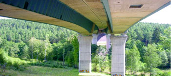
Buckling failure of the web is prevented by the corrugation. The dimensioning of corrugated web beams is given by EN 1993-1-5 Annex D which covers web thicknesses up to 3 mm only.The corrugated steel plate has been used in many fields of application in limited region for a long time because of its favorable properties. For example, in the field of structural engineering it is used as sheet-pile wall or as girder web in building structures. In the field of building design it is used for façades or roof structures, and is used as a basic component in composite floors. For the last 20 years corrugated sheet has been increasingly used as a web in beams. This structural layout has spread in the field of bridges too, especially in hybrid bridges. This is a special bridge type with concrete decks and steel webs, which is mostly corrugated. A schematic drawing of this bridge type can be seen in Fig. 2. The first hybrid bridge with trapezoidally corrugated webs was built in France in 1986 (Pont de Cognac bridge). Because of the great number of advantages, this structural layout spread very fast especially in Japan, where numerous hybrid bridges have been built or are still under construction.
| Due to the features of corrugation, the application of corrugated steel web leads to many advantages for hybrid bridge structures. The web has a small stiffness in longitudinal direction; therefore the pre-stressing force remains in the concrete chords. The resistance against buckling – locally and globally – increases, so the number of stiffeners or diaphragms may be reduced. |
|
In comparison to flat webs there is a high bending stiffness in transverse direction, which allows reducing the number of cross frames in box girder bridges.Due to the increased stiffness the web thickness may be reduced, therefore the dead load of the structure will be smaller leading to easier and faster building processes especially in case of incremental launching. Another advantage is that the difficulty of concreting thin reinforced concrete webs disappears, which also results in a faster and easier building process.
Automatic Fabrication Process
The machines of latest generation are able to produce sinusoidal corrugated-beams by a fully automated process. A more variable design of cross sections, a variety of web thickness, lower beam heights and smaller flange dimensions has become possible. Furthermore tapered beams and machine-made web openings can be produced. There are around 10 major production lines for corrugated web beams around the world, where the automatic production of the following beam dimensions is possible:
- Web height (mm) - 333, 500, 625, 750, 1000, 1250 and 1500
- Web thickness (mm) - 1.5, 2, 2.5, 3, 4, 5, 6
- Flange thickness (mm) - from 6 to 30
- Flange width (mm) - from120 to 450
- Span of the beam (mm) - from 2000 to 5000
- Wavelength of one corrugation (mm) - from 77.5 to 310
The maximum beam length is 16 m which corresponds to the maximum range of welding robots. Usually beams are shorter because of the limitation in transportation, galvanization, etc. For tapered beams the maximum length is 12 m. Due to improvements corrugated webs up to 6 mm thickness has become possible. Therefore the field of application of this beam type has been extended considerably. Even short span bridges are possible now.
| The web material comes in coil. It is unrolled and cut to length automatically by the machine. A so called "corrugator" forms the sheet to a corrugated web. The flanges are parallely prepared and stored in special flange baskets. After the running-in of the web and flanges into the welding station the members are moved to the correct position, are pushed together and are welded by the welding robots. The figure shows the welding of corrugated web beams by |
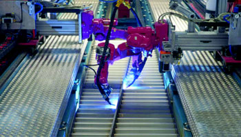 |
robots in an automation production unit.
Advantages of Corrugated Web Beam
Economical design of steel girders normally requires thin webs. The use of corrugated webs is a possible way of achieving adequate out-of-plane stiffness without using stiffeners. Engineers have long realized that corrugation in webs increases the stability of beams against buckling and can result in very economical designs. The web corrugation profile can be viewed as uniformly distributed stiffening in the transverse direction of the beam. When girders with corrugated webs are compared with those with stiffened flat webs, it can be found that trapezoidal corrugation in the web enables the use of thinner webs and corrugated web I-Beams eliminate costly web stiffeners. Although the advantage of the corrugation is not easy to describe in general terms, Hamada (1984) found these beams to have 9 to 13% less weight than current traditionally stiffened girders with flat webs. Because of the less cost and higher load carrying capacity, corrugated web I-beams provide a high strength-to-weight ratio. Furthermore, erection cost is reduced since the corrugation in the web provides higher resistances against bending about the weak axis, and none of the auxiliary lifting equipment normally used are required.
The main advantages and characteristics of the corrugated beam are;
- 40% - 300% weight reduction and saving
- 30% - 200% economy in cost
- Reduced roof dead loads
- Prevention of buckling failure of web due to corrugation
- Lower weight
- Huge architectural capabilities
- Possibility of variable height beams for better usage of the sinusoidal beam strength
Application of Corrugated Web Beam
Corrugated web I-beams have been manufactured and used in Sweden, France, Germany and Japan. In France, corrugated steel webs are being used in composite girder bridges with concrete flanges and corrugated steel web. Recently, Austria began manufacturing and using such beams.Figure 4 shows a large span structure designed by Zeman and Co.
|
|
| Sample projects by Zeman and Co. |
Japan has developed roll forming process to produce corrugated web I-beams and partially corrugated webs which were used in mobile-modular home construction, Hamada et. al, (1984). In United States, beams with corrugated webs are being used widely more and more. Many manufactures are producing such kind of beams. Paik patented the corrugated I-beam and marketed it to builders in 1970s’, and with Sumitomo, a Japanese company that manufactures corrugated I-beam, the beams were manufactured with PACO Engineering Corp. as the exclusive U.S. distributor. Now, many bridges and large span buildings are being built using corrugated web I-beam. For example, Pennsylvania Department Transportation (PennDOT) is sponsoring research adopting corrugated webs to realize additional benefits from High Performance Steel (HPS). It intends to construct a demonstration bridge with corrugated web I-girder.
Design of Beams with Corrugated Web
EURO code 1993-1-5 gives guidelines for design of beams with corrugated web. The Indian Standards does not have any guidelines for design of beams with corrugated web. The discussion is made considering a sinusoidal corrugation for the web.
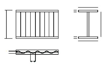 |
| Corrugated web beam with notations |
The profiling of the web generally avoids failure of the beam due to loss of stability before the plastic limit-loading for the web is reached. The sinusoidal corrugation has the advantage over trapezoidal profiling of eliminating local buckling of the flat plate strips. Corrugated web beams may be used as beams (roof or slab beams, structural beams) or as components subject to normal forces virtually without structural limitations. The optimum area of application is in steel structural engineering wherever rolled profiles of structural heights greater than 450 mm or low lattice girders of structural height below approximately 1,800 mm formerly used.
The shear capacity of beam with corrugated web depends on the buckling strength of the web. The failure modes observed are local buckling for large radius corrugations and global shear buckling for dense corrugation profiles. The ultimate moment capacity is based on the flange yield stress. Sometimes the flange yielding is followed by vertical buckling of the compression flange into the web. The steel girders with corrugated webs also exhibit lateral torsional buckling.
Basis for Calculation
As a result of its profiling, the web does not participate in the transfer of longitudinal normal stresses from bending. This means that in static terms, the corrugated web beam corresponds to a lattice girder in which the bending moments and the normal forces are transferred only via the flanges, while the transverse forces are only transferred through the diagonals and verticals of the lattice girder - in this case the corrugated web.
On the basis of this static model, dimensioning is implemented in accordance with EUROCODE 1993-1-5. Accordingly, the verification of the load carrying capacity is ideally provided at the level of internal forces and the cross-sectional resistance of the individual cross-sectional components – i.e., flanges and web.
Design Calculation
Based on the guidelines suggested by EURO code 1993-1-5, the shear and moment capacities of corrugated web beams determined for a web depth of 500 mm, yield strength of 250 MPa and sinusoidal corrugation length of 310 mm are shown in Table 1. The flange width is varied from 200 to 430 mm, while the thickness is varied from 10 to 30 mm. The thickness of corrugated sheets is varied from 2 to 3 mm.
Table 1 : Sectional properties, shear and moment capacities of beams with corrugated beams for web depth h = 500 mm and sinusoidal length W = 310 mm
|
Web depth h 500 mm
|
Flange Dimensions
|
f y = 250 N / mm2 , W = 310 mm
|
|
Shear Capacity (kN)
|
Moment Capacity (kN-m)
|
|
Overall depth H (mm)
|
b x t
(mm)
|
(t=2mm)
|
(t=2.5mm)
|
(t=3mm)
|
|
520
|
200x10
|
83.01
|
112.13
|
143.07
|
183.67
|
|
520
|
220x10
|
83.01
|
112.13
|
143.07
|
202.03
|
|
520
|
250x10
|
83.01
|
112.13
|
143.07
|
229.59
|
|
530
|
220x15
|
83.01
|
112.13
|
143.07
|
306.03
|
|
540
|
250x20
|
83.01
|
112.13
|
143.07
|
468.18
|
|
540
|
300x20
|
83.01
|
112.13
|
143.07
|
561.82
|
|
540
|
350x20
|
83.01
|
112.13
|
143.07
|
655.45
|
|
540
|
400x20
|
83.01
|
112.13
|
143.07
|
749.09
|
|
560
|
350x30
|
83.01
|
112.13
|
143.07
|
1002.09
|
|
560
|
400x30
|
83.01
|
112.13
|
143.07
|
1145.25
|
|
560
|
430x30
|
83.01
|
112.13
|
143.07
|
1231.14
|
Conclusions
The corrugated web girder reduces the use of web stiffeners which results in considerable saving in material. This is mainly due to the use of corrugated sheets for web which increases the buckling strength of web. The usage of thin web further reduces the cost of the structure. The design procedure adopted gives adequate safety factor.
References
- Easley, J. (1975) “Buckling formulas for corrugated metal shear diaphragms”, Journal the Structural Division, ASCE, Vol. No 7, pp. 1403-1417.
- Easley, J., McFarland, D., (1969) “Buckling of Light – Gage Corrugated Shear Diaphragms”, Journal of the Structural Division”. ASCE, Vol. 95, pp. 1497–1516.
- Elgaaly, M., (1983) “Web Design Under Compressive Edge Loads”, Engineering Journal, AISC, Vol. 4, pp 153-171.
- Elgaaly, M., (1997) "Girders with Corrugated webs Under Partial Compressive Edge Loading," American Society of Civil Engineers, Structural Journal.
- Elgaaly, M., (1998) "Steel built-up Girders with Corrugated webs," American Institute ofSteel Construction Engineering Journal, Vol. 35 No.1.
- Eurocode 3 : European committee for standardisation (CEN), 3 Part 1-5 (EN 1993-1-5) Plated structural elements
- Hamada, M., Nakayama, K., Kakihara, M., Saloh, K., Ohtake, F., (1984) “Development of welded I beam with corrugated web,” , Vol. No. 29, pp 75-90.
- Johnson, R.P., Cafolla, J, (1997) “Local flange buckling in plate girders with corrugated webs”, Proceedings of the Institution of Civil Engineers, Structures and Buildings, Vol. 122, No. 2, pp 148-156.
- Lindner, J., (1990) “Lateral-Torsional buckling of beams with trapezoidally corrugated webs”, Proceedings of the 4th International Colloquium on Stability of Steel Structures, Budapest, Hungary.
- Subramanian N., (2009), “Design of Steel Structures”, Oxford University Press, New Delhi.
Acknowledgement: This article by Dr. S. Raviraj, Professor of Civil Engineering, Sri Jayachamarajendra College of Engineering, Mysore, is a part of proceedings of National Seminar on Steel Structures- Steelcon, held at Mysore on 26th and 27th of April, 2013;