Importance of Construction Equipment-A step towards Sustainability
Bureau Built Expressions
Introduction
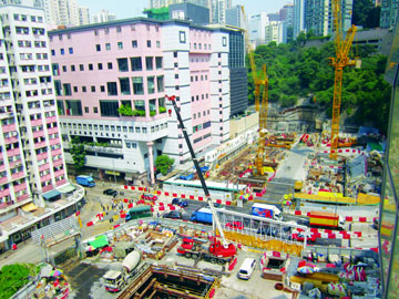
The construction industry today is greatly different from the one of the past. There have been many remarkable changes and advancements not only in terms of the structures that are today being built and the tools that are being used, but most importantly in the techniques and methods that are available now for the actual construction works. In the inevitable scenario of infrastructure development, labour shortage and non availability of skilled manpower, mechanization of construction activity plays vital role. Another area gaining popularity is the mechanisation in respect of vertical transportation of men and material.
Today's tools and equipment have allowed construction worker to eliminate a lot of imperfect mechanisms in construction. Mastery over tools and equipments has definitely increased man's overall productivity. In the absence of many of these modern tools and equipment, professionals are even sceptical whether one can complete some of the modern day projects. Innovations in the field of construction equipment have reached new heights and equipments are being designed considering reduced carbon footprint, air and noise pollution.
 |
Construction activity is an integral part of a country’s infrastructure and industrial development. It includes hospitals, schools, townships, offices, houses and other buildings; urban infrastructure (including water supply, sewerage, drainage); highways, roads, ports, railways, airports; power systems; irrigation and agriculture systems; telecommunications etc. Covering as it does such a wide spectrum, construction becomes the basic input for socio-economic development. Besides, the construction industry generates substantial employment and provides a growth impetus to other sectors through backward and forward linkages. It is, essential therefore, that, this vital activity is nurtured for the healthy growth of the economy.
Proper use of appropriate equipment contributes to Economy, Quality, Safety, Speed and Timely completion of the Project. As construction equipment forms an important part of any construction process, it is not always desirable or possible for the Contractor to own each and every type of Construction Equipment required for the Project. Considering the various aspects of the utility of particular Equipment, the Contractor has to economically justify whether to purchase the Equipment or to hire it. The amount invested in the purchase of Equipment should be recovered during the useful period of such Equipment. In case of large construction projects, proper use of appropriate equipment contributes to economy, quality, safety, speed and timely completion of a project.
Need for Mechanisation
The need for Mechanization arises due to the following reasons:
- Magnitude & Complexity of the Project
- Projects involving large quantities of material handling.
- Complexity of Projects using high grade materials
- High quality standards
- Importance of keeping the Time Schedules.
- Optimum use of Material, Manpower and Finance.
- Shortage of skilled and efficient Manpower.
To maximize the efficiency of mechanized construction, a continuous cycle of transportation and assembly with each type of member must be used to build superstructures. Through repetitions of this cycle, it should be possible to build superstructures quickly and without interruption. To develop mechanized construction systems, the machine systems and material systems to be incorporated must be examined, and the configurations of the building components must be systematized and classified.
Why Mechanisation
Whether a construction contract is unit price, lump sum, or cost-Plus; whether the construction project is to be linear (Concept-Design-Procurement-Construction) or fast tracked (Design-Build), the cost of construction is a major factor in all projects. Major factors that impact construction costs are materials, labour, equipment, overhead, and profit. The cost of equipment for civil engineering projects can range from 25 to 40% of the total project cost.
It is important for design engineers and constructors to be knowledgeable about construction equipment. Construction equipment is an integral part of the construction process and cost of construction is a function of operation. The equipment spread selected for a specific construction operation is critical to the success of a project. Characteristics like Repetitiveness, Health hazards, Lack of skill, Accuracy, Location, Accessibility etc also to be taken into account while making a selection.
A majority of building construction projects experience cost over-runs. Proper planning, involving construction method selection, sequencing operations and coordinating specialty trades, as well as selection and management of proper construction equipment for specific construction tasks and monitoring its production can help effect cost savings. Some of the advantages of building construction mechanisation can be listed as under.
- Higher Speed of Construction
- Timely Project Completion
- Quality Maintenance
- Cost Effectiveness
- Higher Productivity
- Reduced Manpower
- Worker Safety
Equipment Productivity
 |
The manufacturers generally provide the productivity ratings for equipment under different operating conditions. However, it has been realised that the ratings given in the manufacturer’s catalogues represent optimum figures under ideal conditions which can rarely be realised at site. As such it is prudent to use one’s own past experience and judgment and arrive at the probable outputs that can be realised. Such outputs will invariably be lower than the projections given in the manufacturer’s catalogue. To cite an example, the concrete batching plant rated as 30 m³/hr by the manufacturers may at best give 20-25 m³/hr in actual practice. Similarly, using the concrete pump at the rated capacity of 50m³/hr, the field engineer may be able to pump not more than 35m³/hr. Considering these factors, the ratings given the catalogue will have to be multiplied by a utilisation factor which may vary between 60% and 80% in general, depending on the quality of equipment, normal working conditions at site, etc. This is an important factor to be taken into account while deciding on the capacity and the number of equipment to be deployed for each operation.
Having decided pragmatic values for productivity, these can be ensured only if the equipment operation is managed effectively. For performing many of the functions, one needs a series of matching items of equipment. For instance, a typical earth moving operation may involve the use of dozers, loaders, scrapers, dumpers and vibrating rollers. Similarly, in respect of concrete, batching plant, truck mixers, concrete pump and tower crane may be involved. In all such cases, the capacities of various linked up items of equipment should be properly matched in order to obtain the projected output.
Recently, at one of the project sites, it was noted that a hydraulic excavator was being utilised at less than half of its rated capacity. On investigation, it was realised that the excavator was idling for substantial time as there were not enough dumpers to clear the excavated material. In yet another case, concrete was being produced in the batching plant, transported by truck mixers and placed in position using crawler crane and skip buckets. Ever though the capacities of the batching plant, truck mixers and crane were matching the requirements of the job, the output was found to be only half of what was planned. On investigation, it was realised that the concrete bucket was of a much smaller capacity compared with that of the crane and in consequence because of the lack of advance planning concerning a small item, the output of major items of equipment suffered. In the absence of proper planning for the access roads, including their quality for movement of construction equipment, it is a common experience to find low productivity due to bogging down in transit.
Optimum Utilisation of Equipment
Basically, various items of construction equipment are expensive and have to pay for themselves by way of effective utilisation on the projects. Towards this end, it is necessary to plan all aspects of provision, operation and maintenance of construction equipment in advance and ensure that utilisation is as planned. Such planning is usually a cooperative effort involving the owner, the construction agency and the owner of the equipment if he is a separate agency. Even within the organisation of the construction agency, different disciplines have to come together to realise the planning. The project manager, who may be usually a civil engineer and the plant engineer at the project site, will need to have a continuous dialogue during all stages of planning and execution. Continuous review and revision of the plant allocation may be called for, based on changes in field conditions.
Equipment Cost
The cost of project must include the deployment of necessary equipment and the rates be quoted accordingly. While including the equipment cost, constructor should consider repetitive and depreciation components of the equipment output. Depending on the size of the project, the constructor can either lease/rent the equipment or own the equipment. In case of leasing option, following are to be examined and considered.
- Time factor- whether the rate quoted is for one shift or two shifts or per month etc
- Cost of Repairs-Clear understanding to be arrived at in respect of repairs, maintenance, consumables etc.
- Operator-Usually accompanies the equipment.
- Fuel and Lubricants- usually Lessee’s responsibility
- Freight Charges- Whether delivery at site or transportation extra
- Insurance-It is standard practice for the lessee to furnish the lessor a certificate of insurance prior to the delivery.
Selection Criteria
Factors affecting the selection of construction equipment can be listed as below;
- Availability of equipment.
- Suitability of job condition with special reference to climatic and operating condition.
- Uniformity type (easier operation and maintenance, easy exchange of spare parts and operating personnel)
- Size of equipment.
- Use of standard equipments (made by several companies so that easy purchase and delivery)
- Country of origin. (If importing foreign exchange facility should be easily available)
- Unit cost of production – cost of running
- Availability of spare parts and selection of manufacturer.
- Availability of local labour for operations.
Current Status
 |
The Indian Construction Equipment sector has an estimated market size of US$ 2.4 – 2.6 billion for the year 2007. The industry has been growing due to the large investments made by the Government and the private sector infrastructure developments. The prospects of the construction equipment industry look attractive with a projected investment of US$ 320 billion in the infrastructure sector over the next few years. T
he Indian market is catered by about 200 domestic manufacturers (small, medium & large).Though the Indian construction equipment industry is a fraction of the global market, whose size is over US$ 75 billion, it has been growing at an average of 30 per cent annually compared to the global growth of 5 per cent. India is one among the top 10 markets for construction equipment and is one of the key international markets.
|
The growth in this industry is expected to be primarily due to investments in infrastructure, investments by the Government in the form of external borrowings and internal accruals by Public-Private-Partnerships (PPP) model. Indian firms are strengthening their existing operations for catering to the growing domestic demand and are also planning to expand to tap overseas markets. At the same time international majors have ambitious plans for India.
As per data by industry reports, India builds an average of 8.7 billion sq ft of real estate space every year or about 95 billion sq ft in the current decade from 2010-20. In 2010, the annual requirement stood at 7.3 billion sq ft, which will be touching 10.15 billion sq ft by 2020. Reports also state that the housing sector has a requirement of 85 percent of potential space requirement, but faces a shortfall of 26 million units. This will lead to India having a cumulative demand of 2.3 million units in next five years, against supply of one million units.
The Adaptability Factor
 |
Experts indicate that "in the case of metros and cosmopolitan towns, due to constraint of site and geographical locations, customers are forced to use a variety of machinery to execute the construction projects. But in case of Tier III and IV cities, it is observed that the mechanisation is related to mixing and lifting of concrete; placing and compaction has been done manually. Material lifting is partly done manually and partly by machine; bar-bending and cutting in majority of locations has been done manually, but now is slowly changing to machines due to speed and economy factors." |
It is also observed that some of the construction activities related to excavation of trenchless boring, plastering, curing, bar bending, bar cutting, concrete placing and compaction, Lifting of materials such as sand and bricks, clearing of construction material debris are all also lag behind.
Activity Based Classification
In the present construction industry scenario, it is a common fact that we find a wide variety of construction machinery available for various tasks, which make the construction jobs easy, safe and quicker. Depending on the application, construction machines are classified into various categories which we are listed here. Though it is not possible to discuss all equipment in this article, important equipment and tools required for construction mechanization are briefed here.
- Surveying equipment
- Modern laser tools
- Miscellaneous tools
- Earth-moving equipment
- Compaction equipment
- Hauling equipment
- Hoisting equipment
- Pumping equipment
- Aggregate Washing equipment
- Concrete production/transport equipment
- Pile-driving equipment
- Tunnelling and rock drilling equipment
- Pumping and dewatering equipment
- Precasting Yard equipment
- Vertical transport equipment
- Asphalt Mixing Plant
- Asphalt laying equipment
Equipment for complete mechanisation
1. Surveying Equipment
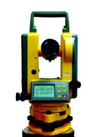
Theodolites
A theodolite is an instrument for measuring both horizontal and vertical angles, as used in triangulation networks. It is a key tool in surveying and engineering work, particularly on inaccessible ground. A modern
Theodolite consists of a movable telescope mounted within two perpendicular axes - the horizontal or turn-on axis and the vertical axis. When the telescope is pointed at a desired object, the angle of each of these axes can be measured with great precision, typically on the scale of arc seconds.
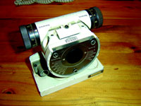
- Total Stations A total station is an electronic/optical instrument used in modern surveying. The total station is an electronic theodolite (transit) integrated with an electronic distance meter (EDM) to read distances from the instrument to a particular point where an assistant staff holds reflector. Robotic total stations allow the operator to control the instrument from a distance via remote control. This eliminates the need for an assistant staff member as the operator holds the reflector and controls the total station from the observed point.
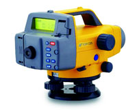
- Automatic level It is an instrument to take levels of any surface. Good level instrument shall have property of automatic horizontal adjustment of the line of sight, an erect figure and a horizontal circle of 0 - 360° and large ribbed control buttons to simplify the ajustment of the instrument. The compensator shall be magnet damped, so that after the instrument has been set almost horizontal, the line of sight can be carefully levelled using the automatic compensation mechanism.
- Abney Levels A Topographic Abney Level is an instrument used in surveying which consists of a fixed sighting tube, a movable spirit level that is connected to a pointing arm and a protractor scale. The Topographic Abney Level is used to measure degrees, percent of grade, topographic elevation and chainage correction. By using trigonometry the user of a Topographic Abney Level can determine height, volume and grade. The Topographic Abney Level is used at the eye height of the surveyor and is best employed when teamed with a second surveyor of the same eye height. This allows for easy sighting of the level and greater accuracy.
- Clinometers Clinometers is an instrument for measuring angles of slope (or tilt), elevation or inclination of an object with respect to gravity. It is also known as a tilt meter, tilt indicator, slope alert, slope gauge, gradient meter, gradiometer, level gauge, level meter, declinometer and pitch & roll indicator. Clinometers measure both inclines and declines.
2. Earth Excavators
Excavators fall under heavy equipment category and consist of a boom, bucket and control cab on a rotating platform. The cab which sits on top of an under carriage with tracks or wheels, controls all movement and functions of the excavator and are accomplished through the use of hydraulic fluid, be it with rams or motors. Excavators are used in many ways and for many purposes by changing the attachments.
- Digging of trenches, holes and foundations
- Material handling
- Brush cutting with hydraulic attachments
- Forestry work
- Demolition
- General grading/landscaping
- Heavy lift, e.g. lifting and placing of pipes
- Mining, especially, but not only open-pit mining
- River dredging
- Driving piles, in conjunction with a Pile Driver
Types of Excavators can be listed as below:
- Compact Excavator
- Crawler Excavator
- Wheeled Excavators
- Backhoe Loader
- Dragline Excavator
- Bucket Wheel Excavator
- Long Reach Excavator
- Power Shovel
- Suction Excavator
Descriptions and other parameters related to Excavators are since available in plenty, these are not dealt in detail in this section.
3. Dozers
 |
Powerful machine for pushing earth or rocks, used in road building, farming, construction and wrecking; it consists of a heavy, broad steel blade or plate mounted on the front of a tractor. Sometimes it uses a four-wheel-drive tractor, but usually a track or crawler type, mounted on continuous metal treads, is employed. The blade may be lifted and forced down by hydraulic rams. |
4. Bulldozers
Bulldozer, which pushes earth and rocks with a blade installed at the machine’s front end. Large- sized crawler dozers normally have a set of claws called a ripper that is installed at the machine’s rear end and can crush a hard rock. Swamp bulldozers are equipped with an undercarriage that is configured to enable them to freely move around on a marshy land. As a fellow machine, there is a pipe- laying machine that lays down a large steel pipe in the construction of a pipeline and a dozer shovel (crawler loader) for loading.
5. Rollers
Single Drum Vibratory Rollers - are used to compact all types of soil with the exception of rock fill. The rollers are suitable for most types of road construction, airfields, dam construction, harbour projects and industrial constructions. Heavy-size vibratory rollers are used for a very wide range of applications.
Road roller - Road rollers use the weight of the vehicle to compress the surface being rolled. Initial compaction of the substrata is done using a pneumatic tyred roller, with two rows (front and back) of pneumatic tyres. The flexibility of the tyres, with a certain amount of vertical movement of the wheels, enables the roller to operate effectively on uneven ground. The finish is done using metal-drum rollers to ensure a smooth, even result.
There are different types of rollers available in the market based on the principle of compaction they adopt. Some of them are: Walk behind Rollers, Ride-on Rollers, Vibratory rollers, Pneumatic-tyre rollers, Tandem Rollers etc. Engineers have to chose based on the nature of soil to be compacted.
Sheepsfoot Rollers
These rollers are also called pad-foot rollers. They are used to compact fine-grained soils such as clays and silts, as well as mixtures of sand and fine-grained soils. The sheepsfoot roller is a steel wheel that has a number of steel projections, or feet, welded to it. The Sheepsfoot roller compacts the soil by kneading it. The feet on the roller can sink through loose soil to a depth of approximately 10" (250 mm). These rollers work best, therefore, when the lift thickness is between 6" and 10" (150 and 250 mm). Lifts of this thickness allow the feet to sink through the loose material and knead it into the lift below, while the smooth surface of the wheel compacts the soil on the surface of the lift. As the lower portion of the lift becomes compacted, the feet ride up into the upper portions of the lift and compact it. Because of the manner of compaction, it is best not to compact a lift all the way to the top surface. By leaving the surface material loose, a better bond will be achieved between that lift and the next lift that is placed.
Like steel-wheel rollers, sheepsfoot rollers can be static or vibratory, and come in several different models. The most common models are self-propelled, tandem, four wheel, and towed. In addition, some sheepsfoot rollers come with small bulldozer-type blades, which allow the roller to perform rough grading or backfilling as it compacts the soil.
6. Compactors
Manually operated compactors have a number of different applications. They are used in areas where it is not possible to use a full size compactor. This includes such applications as compacting the fill over a trench, compacting soil around a footing, or working in areas where large equipment might cause damage to adjacent structures or property.
Manually operated compactors come in a number of different styles depending on the application. There are small steel-wheel rollers, vibratory plate compactors, and rammers. While these smaller compactors allow the Contractor to work in small areas, they require more time and effort to compact the material to the required density. The use of full-size equipment is generally preferred where possible.
Earth compactors - are designed for diverse application in compacting soil, sand and breaking stone. Therefore these earth compactors are ideal for construction purposes and road projects since these works require compaction. Earth compactors are used for compaction of top layer of earth.
Plate Compactors - are particularly suitable for application like compacting loose gravel and sand on footpaths, sub-grade for concrete floors, trenches, column footings & for small repair works like pot-hole repairs.
7. Grader Equipment
Auger Boring Machine
A grader is also known as a road grader, a blade, a maintainer or a motor grader. This is a construction machine with a long blade used to create a flat surface. Graders can produce inclined surfaces, to give cant (camber) to roads. In some countries they are used to produce drainage ditches with shallow V-shaped cross-sections on either side of highways. Graders are commonly used in the construction and maintenance of dirt roads and gravel roads. In the construction of paved roads they are used to prepare the base course to create a wide flat surface for the asphalt to be placed on. Similarly, graders are used for leveling the surface during earthwork is embankments and providing blanket surface before spreading ballast and laying track. Graders are also used to set native soil foundation pads to finish grade prior to the construction of large buildings and for underground mining. Capacities range from a blade width of 2.50m to 7.30 m and engines from 93–373 kW (125–500 hp).
8. Tunnelling Equipment
Double Shield Tunnel Boring Machine (TBM)
Tunnelling equipment is a machine used to excavate tunnels with a circular cross section through a variety of soil and rock strata. There can bore through hard rock, sand and almost anything in between. Tunnel diameters can range from a meter (done with micro-TBMs) to almost 16 meters. Tunnels of less than a meter or so in diameter are typically done using trenchless construction methods or horizontal directional drilling. Tunnelling equipment has limiting disturbance to the surrounding ground and producing a smooth tunnel wall. This significantly reduces the cost of lining the tunnel and makes them suitable to use in heavy urbanized areas. The major disadvantage is the upfront cost. TBMs are expensive to construct and can be difficult to transport. However, as modern tunnels become longer, the cost of tunnel boring machines versus drill and blast is actually less-this is because tunnelling with TBMs is much more efficient and results in a shorter project period. Type of tunnelling equipment:
- Auger boring machine
- Gripper tunnel boring machine
- Double shield tunnel boring machine
- Single shield tunnel boring machine
- Earth pressure balance tunnel boring machine
- Microtunneling boring machine
- Slurry pressure balance tunnel boring machine
- Mixshield tunnel boring machine (TBM) Aker Wirth
Auger Boring Machine
An Auger Boring Machine (ABM) is used to bore horizontally through soil or rock with a cutting head and auger. The majority of ABMs are used to install pipe casing under railroads, highways, airport runways, creeks or any area of ground that cannot be open cut or disturbed in any way. There are many types of cutting attachments for this machine. They range from Backhoe Teeth cutters for cutting through soil to the Small Boring Unit for boring hard rock.
Initially the ABM is set up in the starting pit on a predetermined length of track. A backing plate, usually steel or reinforced concrete block is installed in the wall opposite of the boring to withstand the thrust exerted by the boring machine. The machine bores through the earth with a cutting head and the jacking force is provided by the hydraulic thrust. The pipe casing and auger sections are added as the machine advances. Spoil is removed from the auger through the casing to a door located on the side of the machine.
Gripper Tunnel Boring Machine (TBM)
Earth Pressurrre Balance Tunnel Boring Machine (EPB TBM)
Main Beam of TBM is complex in its design, yet relatively simple in concept. The front of the TBM is a rotating cutter head that matches the diameter of the tunnel. The cutter head holds disc cutters (ranging from 11" to 20" in diameter) which are positioned for optimal boring of the given rock type. As the cutter head turns, hydraulic propel cylinders push the cutters into the rock. The transfer of this high thrust through the rolling disc cutters creates fractures in the rock causing chips to break away from the tunnel face. A unique floating gripper system pushes on the sidewalls and is locked in place while the propel cylinders extend, allowing the main beam to advance the TBM. The machine can be continuously steered while gripper shoes push on the sidewalls to react the machine's forward thrust. Buckets in the rotating cutter head scoop up and deposit the muck on to a belt conveyor inside the main beam. The muck is then transferred to the rear of the machine for removal from the tunnel. At the end of a stroke the rear legs of the machine are lowered, the grippers and propel cylinders are retracted. The retraction of the propel cylinders repositions the gripper assembly for the next boring cycle. The grippers are extended, the rear legs lifted, and boring begins again.
Double Shield Tunnel Boring Machine (TBM)
A Double Shield TBM consists of a rotating cutter head mounted to the cutter head support followed by three shields: a telescopic shield (a smaller diameter inner shield which slides within the larger outer shield), a gripper shield and a tail shield. In normal operation ("double shield mode"), the gripper shoes are energized, pushing against the tunnel walls to react the boring forces. The main propel cylinders are then extended to push the cutter head support and cutter head forward. The rotating cutter head cuts the rock.
The telescopic shield extends as the machine advances keeping everything in the machine under cover and protected from the ground surrounding it.
The gripper shield remains stationary during boring. A segment erector is fixed to the gripper shield allowing pre-cast concrete tunnel lining segments to be erected while the machine is boring. The segments are erected within the safety of the tail shield. It is the Double Shield's ability to erect the tunnel lining simultaneously with boring that allows it to achieve such high performance rates. The completely enclosed shielded design provides the safe working environment.
If the ground becomes too weak to support the gripper shoe pressure, the machine thrust must be reacted another way. In this situation, the machine can be operated in "single shield mode". Auxiliary thrust cylinders are located in the gripper shield. In single shield mode they transfer the thrust from the gripper shield to the tunnel lining. Since the thrust is transferred to the tunnel lining, it is not possible to erect the lining simultaneously with boring. In the single shield mode, tunnel boring and tunnel lining erection are sequential operations.
Regardless of the operating mode, working crews remain protected within the shields. Double Shield TBMs are capable of safely excavating a wide range of geologic conditions on a project. Double Shield TBMs are manufactured to suit project requirements, in diameters from 1.6 m to 15 m (5 to 50 ft).
Single Shield Tunnel Boring Machine (TBM)
Single Shield TBMs protect workers from broken rock until the tunnel lining can be safely installed. The body of the machine is enclosed in a shield that is marginally smaller than the diameter of the tunnel. The flat, low-profile cutter head minimizes disturbance of the face as it bores and prevents large blocks from collapsing and causing excessive boring stresses. The front of the TBM is a rotating cutter head that matches the diameter of the tunnel. As the cutter head turns, a ring of hydraulic cylinders provides forward thrust through shoes that push against the tunnel lining.
The cutter head holds disc cutters (ranging from 11" to 20" in diameter) positioned for optimal boring. The transfer of high thrust through the rolling disc cutters creates fractures in the rock, causing chips to break away from the face. Boring and lining installation are performed sequentially. To steer, cylinders orient the articulated cutter head in the required direction.
Single Shield TBMs are available in diameters from 1.6 to 15 m (5 to 50 ft). All Single Shields are equipped with high-speed segment erectors for rapid tunnel lining installation. To steer the machine, the cutter head is articulated. The short shield length enables a small turning radius and minimizes exposure to squeezing ground forces that could potentially trap the machine.
Earth Pressure Balance Tunnel Boring Machine (EPB TBM)
If the geology ranges from soft soils to weathered rock, then Earth Pressure Balance Machine (EPBM) is the correct technical solution for project. This is particularly true when project is located in an urban environment and ground surface subsidence cannot be tolerated. EPBMs are utilized in the construction of rail tunnels, metropolitan subway systems, highway tunnels, and other projects where the tunnel will be constructed either partly or completely in soft soil beneath the water table.
From "Smooth Flow" cutter heads that reduce friction to super-reliable sealing systems and Variable Frequency Cutter head Drives, has taken the traditional EPB design to the next level.
Microtunneling Boring Machine (MTBM)
Small Boring Units (SBU-A) is a small diameter rock cutting head (from 24"/600 mm to 72"/1.8 m) that can be used with any Auger Boring Machine (ABM) to excavate hard rock on drives less than 500 ft (150 m). SBU-A has been proven on hundreds of jobs across the U.S. Over one hundred contractors in locations around the world have proven the SBUA works better than any other method of excavating small diameter, hard rock bores.
Slurry Pressure Balance Tunnel Boring Machine (SPB TBM)
Bentonite slurry, consisting of a specific clay and water mixture is universally used in boring and digging operations. The slurry has numerous properties: sealing of the cutting face, reduced friction on the TBM's structure and transport of cuttings to the separation plant outside the tunnel.
The basic principle of this TBM is to maintain the tunnel's cutting face during the excavation phase by filling the working chamber, located behind the cutter head, with slurry.
Slurry pressure is carefully controlled by a large air bubble which is maintained by a separately-controlled air supply system. This air bubble acts as a damper by absorbing sudden variations in mucking output.
Mix shield Tunnel Boring Machine (TBM)
Dual mode-two process technologies in one as the term 'dual mode' indicates, two process technologies are combined in these machines.
- Shield machines - these machines are externally similar to shield machines and combine the functional features of a hard-rock shield tunnel boring machine and optionally, of a slurry shield or a hydro shield machine. They are always used when tunnels have to be driven alternately in stable and unstable sections.
- New style machines: Dual-mode tunnel boring machines are still a new type of machines and have been developed to meet the requirements of complex projects in strongly varying geologies. Where conventional tunnelling techniques had to be used formerly, these machines now open the way to lower-risk and lower-cost tunnelling in difficult geological conditions.
9. Cranes
Different types of equipment ranging from Tower Cranes to Lifting Hoists to simple site fabricated systems using electrically or mechanically operated winches can be adopted. They are frequently used for shifting of concrete, masonry blocks, labour, reinforcement and many other miscellaneous materials.
The construction equipment that falls under the term “cranes” represents a broad class of machines. The typical crane is used to lift and place loads. Modifications on the basic crane structure allow it to be used for other activities such as dredging and pile driving.
A crane is a lifting machine, generally equipped with a winder (also called a wire rope drum), wire ropes or chains and sheaves that can be used both to lift and lower materials and to move them horizontally. It uses one or more simple machines to create mechanical advantage and thus move loads beyond the normal capability of a human. Cranes are commonly employed in the construction industry, lifting of heavy material, girders etc. Different types of cranes available are:
- Truck mounted Cranes
- Rough Terrain cranes
- Side Lift Cranes
- All terrain cranes
- Crawler Cranes
- Floating Cranes
- Loader Cranes
- Tower Cranes
- Lifting Hoists
Tower Cranes
India is witnessing construction of a large number of high rise structures including Tall Buildings, Power Station chimneys, Natural Draught Cooling Towers, Elevator Towers and the list goes on. The use of Tower Cranes in all such cases becomes an absolute necessity. While some Tower Cranes are being manufactured and assembled in India, cranes to serve the upper end of the construction spectrum are still being imported.
Tower Cranes are being extensively used for material handling and concreting. Their configuration offers several advantages over more traditional cranes, including reduced space requirements, higher vertical lift, increased capacities and quiet electrical operation. In high-rise buildings, tower cranes can route through the elevator shaft, further easing space requirements. Tower cranes are available in several common types, each with its own advantages.
Tower cranes now-a-days are sophisticated items of construction equipment, requiring detailed planning in procurement and utilization. They are electrically operated and come with wide variety of options both in terms of working range, jib arrangement, mass configuration etc. Some aspects of the various issues are now dealt with in the paper.
Types of Tower Cranes
- Hammerhead Crane - A hammerhead crane is the most common and often associated with a tower crane. A long horizontal jib is attached to a vertical tower. One end of the jib extends horizontally over the worksite, while the other end has a counterweight. A trolley, which holds the lifting cable, travels along the length of the jib, and a tower crane can operate anywhere within the jib's radius. The operator rides in a cab at the intersection of the jib and tower. Hammerhead cranes typically require a second crane to assemble and disassemble them at the worksite. Self-lifting hammerhead cranes can insert and remove sections to their tower and change their height.
- Self-Erecting Tower Cranes - A self-erecting crane can completely assemble itself at the job site without the need for a second crane. This provides an advantage in setup time and equipment costs. While some versions have an operator cab on the jib, self-erecting cranes are often remote-controlled from the ground. Self-erecting cranes are usually freestanding, and can be equipped to move around the job site. Some self-lifting cranes also have a telescoping tower, which allows the crane to work at multiple heights without reconfiguring the tower.
- Luffing Jib Tower Crane - In tight urban work spaces, there is often insufficient clearance for the jib to rotate without being blocked by existing buildings. For such spaces, a luffing jib tower crane is used. While most tower cranes have a fixed horizontal jib, the operator can raise or lower a luffing jib to allow the crane to swing in a reduced radius. A luffing jib does not use a trolley like a conventional tower crane, but rather raises or lowers the jib as needed for lifts closer to the tower. Because of the added complexity, luffing cranes are more expensive, and only used when needed.
- Brief Description - Tower crane is the only type of crane specially designed for buildings and other high rise structures. They can distribute material for whole plan area of a tall structure. Tower cranes can be fitted with a derricking jib or horizontal jib with traversing trolley. A derricking jib is necessary if required to be raised to clear obstructions. A horizontal jib is easier to operate, is faster and has lower power consumption. In such cases the designer of the building should permit attachment with resultant loads, at appropriate points. With winches of higher capacity, the maximum height of the attached crane can be increased.
- Choosing the right type of Tower Crane - Tower cranes feature a high manoeuvrability, a large space below the crane and high arrangement of the boom which can pass over the erected structures.
The type and number of cranes to be used will depend on the plan, size and shape and the height of the building and the access spaces around it. Where the tower crane is located outside a high rise structure, it is often have to be tied to the structure at intervals to stabilize the mast. The structure assists in taking up the reaction at a certain points, in which case the structure has to be designed for the stresses generated by the anchors.
Over head or Gantry Cranes
These cranes are generally used involving large span service areas and are free from floor obstructions. They are widely used in erection, foundry, steel plants, storage yards and different types of industrial works. These type of cranes consist of two main parts i.e., the bridge and the crab. The bridge consists of two main girders fixed at their end to end and capable of moving on gantry rails. The crab consists of the hoisting gear mounted on a frame. The frame itself is mounted on another set of wheels and capable of travelling across the main girder.
10. Concrete Equipment
The role of concrete equipment plays a very vital role in the construction industry and they vary from simple 10/7 mixers to complicated, computerized batching plants. Concrete production involves batching, mixing, handling and transportation, placing, finishing curing as per the desired specifications.
Concrete Pumps
Concrete dumpers
- Hand fed tilting mixers - These are the smaller capacity mixers. Aggregate, cement and water are fed into the drum by hand. The revolving drum with its mixing blades gives a lifting, combing and agitation to mix the concrete.
- Loader fed tilting drum mixer - These mixers are of larger capacity as compared to the fed tilting drum mixers. Mixer is fitted with a loading hopper operated by rope. Mixing drum is supported on solid iron yoke and can tilt either side.
- Reversing Drum mixers - These are used in larger work. This machine comprises of two sets of blades, one blade mixes while drum is rotated while the other discharges the mix when drum is rotated in reverse.
- Roller Pan Mixer - These are used for mortar mixing in general. The roller and mixing blades rotate in a pan and not only mix the material but also produce a kneading and crushing action. The drive to the rollers and mixing blade is provided by either diesel engine or electric motor.
- Transit Mixers - Concrete mixed is transported from the batching and mixing plant to site. Fully or partly mixed concrete is transported through truck mixers, when the construction site is far from batching plant. Entire mixing is carried in journey. Addition of admixtures helps concrete not to set due to delays in transportation. However, concrete thus mixed and carried should be used within 3 hrs preferably.
- Concrete dumpers - Concrete Dumpers are used to carry mix from concrete mixer to site. Mixer is kept near the site from the concrete dumpers. These are used for short leads only. This Dumper may be two wheel or four wheel drive propelled by diesel engine has a low centre of gravity.
- Concrete Pumps - Concrete Placement Speed is always an important factor and one of the benefits of using concrete pumping is that it helps to place the concrete more accurately without involving much of a labour. Since the cohesive nature of the concrete mix is one of the necessities for mixing, we are assured of a good concrete. In case of high rise buildings, multi-stage pumps are also used. There are many projects where the concrete pump is directly placed below the batching plant and the concrete pipe line is connected to the location of pour. Capacities of these pumps vary in terms of their delivery. Depending on the way the concrete is transported, concrete pumps are classified in two basic types; the boom pump and the line pump. The boom pump uses a remote controlled robotic arm to place concrete where it needs to go, and they’re often used in large construction projects. Boom pumps are able to pump concrete at high volumes and are extremely accurate, which is why they are used for larger projects.
- Placer Booms - Placer Booms are self-contained units consisting of a truck and frame, and the pump itself. These are used for concrete pours for everything from slabs and medium high-rise buildings, to large volume commercial and industrial projects. They range from single-axle truck mounted pumps used for their high maneuverability, suitability for confined areas, and cost/performance value, to huge, six-axle rigs used for their powerful pumps and long reach on high-rise and other large-scale projects. Booms for these trucks can come in configurations of three and four sections, with a low unfolding height of about 16 feet. This low unfolding height is ideal for placing concrete in confined areas. Longer, five-part booms can reach up or out more than 200 feet. Because of their reach, boom trucks often remain in the same place for an entire pour. This allows ready mix trucks to discharge their loads directly into the pumps hopper at one central location and helps to create a more efficient jobsite traffic flow.
- Line Pumps - These pumps require steel or rubber concrete placing hoses to be manually attached to the outlet of the machine. Those hoses are linked together and lead to wherever the concrete needs to be placed. Line pumps normally pump concrete at lower volumes than boom pumps. The capacity of the pump varies from model to model and depends on the volume of concrete it delivers at the end point per hour.
- Batching Plants - A concrete batching plant is special form of machinery designed to homogeneously mix various ingredients for formation of the right concrete mixture that can be used in various applications. Types of Concrete Batching Plants Depending on the how the concrete in mixed and when the concrete reaches the construction site, the concrete plants are mainly classified into two categories - ready mix concrete plant and central mix concrete batching plant.
In a ready mix concrete plant, dry form of concrete excluding water is mixed thoroughly. This dry concrete is then transported in a concrete transport truck to the construction site. Water is added to this dry concrete mixture when the truck is on its way to the job site.
Transit mixers
The another popular form of concrete batching plant is a central mix concrete plant in which either all or only a few ingredients of concrete are mixed along with water at a fundamental location where the plant is situated. This mixed concrete solution is then disposed to the job site for construction purposes. This is usually a high capacity batching plant, which generally consists of silos, bins, concrete batchers, conveyors and control equipment. They are stationary mixer units as compared to the mobile batching plants which consist of frameworks carrying batchers, conveyors, scales, control equipment, small silos and are normally adapted to be transported from site to site.
Batching Plants
- Vibrator - For compacting the concrete after its placement concrete vibrator is used. It help volume of concrete quickly placed, give high density, reduce air voids. Types of Vibrators;
- Internal vibrators-Use on large work for flat slab.
- External or form vibrators-uses for thin section of walls.
- Surface vibrator-used to finish concrete surface such as bridge floor, road slab, section platform.
- Table Vibrator-used for consolidation of precast units.
11. Bar Bending and Shearing Machines
The cutting and bending of steel is one of the most important activities in any kind of construction or infrastructure projects. This could be done on site manually or mechanically. In the traditional method of cutting and bending, there is a possibility of inaccuracies creeping in. This is avoided by using Cutting and Bending machines. Reinforcement bars of various diameters (ranging from 6 mm to 40 mm) are cut and bent as per the bar bending schedule. We find bending and cutting machines separately in the market while there are also machine performing dual duties. The machine usually consists of electrical panel board, limit switch, emergency stop and indicator. Different dies are provided for different sizes of bar. Skilled and trained operators are needed to operate these machines.
12. Power Floats
A power trowel, also known as a "power float", "helicopter" or "trowel machine", is used to obtain a smooth, uniform, flat surface doing away with manual inaccuracies. Power trowels can be generally classified based on the way they are controlled.
- Ride-on power trowels are operated by an operator seated on the machinery and controlling power trowel movement.
- Walk-behind power trowels are used by an operator walking behind the machine.
It is mandatory to level and compact the concrete surface prior to the use of Power Trowel. It is also essential to trowel at the correct time. The operator must wait until the soft concrete hardens sufficiently to take the weight of the machine and the operator.
The trowel is fitted with either float blades or floating disc at the time of Floating, which is the first pass. The operation during the floating pass should be slow and uniform. This is then followed by the second pass to remove any marks due to disc movement. Once the surface has been 'floated', the blades of the trowel are changed to finishing blades. The finish pass should be started when the surface has dried off, and walking on the surface leaves no appreciable indentations.
For the finishing pass the blades are angled to suit the concrete, increasing the angle after each pass - an angle of around 5-10º is usual, the steeper the angle the harder the finish. Several passes with the finish blades may be required to achieve the specified finish.
13. Pile Driving Equipment
Power Float
Bar Bending Machines
A pile is a structural member that is driven into the ground to provide support for a structure. Piles are made from timber, concrete, or steel, and come in a variety of shapes and sizes. They can be driven into the ground vertically or at an angle. The material, size, and angle of the piles used on a Project are determined during the design phase. These characteristics will impact the type of pile driving equipment that the Contractor uses.
Pile Driving Equipment
The ground material the piles are driven into also impacts the choice of pile driving equipment. Piles can be driven through gravel, sand, or fine-grained soils with a range of moisture contents. During driving, friction will build up between the ground material and the pile. The amount of friction expected, as well as the material present, will play a role in determining the best type of pile driving equipment.
Cross line Laser Levels Rotary Laser Levels
A kind of ground treatment for strengthening the ground soil and makes it capable of supporting the load of building is called piling. It involves the driving of pile into ground below the ground level. Generally, concrete piles, timber piles, steel piles and bored piles are used to make the soil stronger for holding the weight of a building. On the other hand, sheet piles act as supporting wall due to ability of sustaining the lateral load. Specially designed piling equipment can be used for driving piles into the ground.
 |
Piles are installed by a special pile driving device known as a pile hammer. The hammer is usually suspended from the boom of a crawler crane, supported on a large frame called a pile driver or carried on a barge for construction in water. The hammer in general is guided between two parallel steel members called leads. The leads may be adjusted at various angles for driving vertical and batter piles. |
14. Modern Laser Tools for Effective Results
- Square line / Tiling Laser
- Cross line Laser Levels
- Dot Lasers
- Rotary Laser Levels
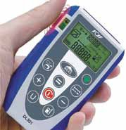
- Laser Distance Meters
- Inclinometers
15. Tools for Effective Productivity
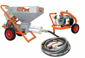 |
Plaster Spray Machines-Plaster sprayers enable us to apply plaster up to five times faster than traditional methods and can reach 80 meters height. Most of the plaster spray machines prefer ready mix plaster. Plastering Machine is particularly designed for the building and construction industry to improve work efficiency and effectiveness. Below are the advantages of using plastering machine:
|
- Better quality plastering.
- Eliminates leakage, cracking and peeling off dried plaster.
- Helps in reducing manpower.
- Faster.
- Low maintenance & low downtime
These spray machines can also be used for internal plastering with gypsum based mix in which case regular washing of the equipment is required.
 |
Auto Rendering Machines - Auto rendering machine provides high quality wall rendering. Machine can achieve mortar coating and smoothing in the same time. When effectively used, it can deliver up to 500 sqm per day of plastered surface. Some of the salient features of Automatic Rendering Machine are; It can reach the very top of the roof- Combine with the screw and conveying belt to achieve the vibrating compaction- Fast positioning- Hydraulic lifting methods to improve the stability of the machine- If the cable fall off, the machine will stop automatically- Larger hopper, more materials can be loaded.
|
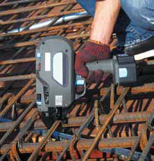
Rebar Tying Tool- These are normally rechargeable- battery operated hand held tools used for tying the rebars. They are capable of making one tie per second and very effective with 16 gauge GI binding wire.
Conclusion
There are several other construction equipments used in the construction industry that are beneficial and help us in achieving optimum performance. The choice of using suitable machinery depends upon the awareness of availability of such machines in the market. Several tools like concrete chippers, hacking tools, grove cutting machines, shotcrete equipment, grouting pumps, wagon drilling equipment, Dewatering pumps etc to be considered while planning a fast track project.
FACT SHEET
The equipment rental and leasing business in India is smaller compared to Japan, USA and China
- Demand for rental equipment is set to witness strong growth in the medium term due to large investments in infrastructure.
- New players can also explore opportunities in the equipment finance business
- The global average of revenues from after-sales service is 12-20 per cent; in India it is 2-8 per cent
- After-sales market is set to expand to USD0.5 billion by 2015; players can offer maintenance contracts with improved pricing and execution
- While these services contribute only modestly to revenues, they are counter-cyclical and can also boost spare part sales
- Export opportunities are abound – both in developed and emerging economies
- Components and aggregates export is a USD 1 billion opportunity; local suppliers can gain a decent share of this by exporting engineering-intensive and basic material based components
- Opportunities in engineering and design off shoring and equipment exports may arise in the future
- Fundamentals for the sector are set to remain strong on the back of increasing infrastructure investments
- Almost all global technology leaders in the construction equipment sector have a presence in India either as joint ventures or with their own manufacturing or marketing companies.
- Joint ventures with global majors have provided domestic companies access to advanced technology and a whole gamut of project management experience
References:
- Totally Mechanized Construction System for High-Rise Buildings (T-UP System) by S. Sakamoto and H. Mitsuoka
- Earthwork Equipment Manual
- Presentations by Prof.dr.Nerman Rustempasic and Ahmed El Sayed
- Presentations by Dr.U.J.Kahalekar
- Presentations by Ashish parihar, Hunsraj bhalekar
- Construction Industry in 2013-11-07
- Benefits of concrete pumping presentation.
- Construction Equipment Guidelines by IBEF
- Compendium of Construction Equipment by Indian Railways.