The Pir Panjal-An Engineering Marvel, Truly Amazing
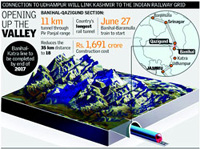
India's longest railway tunnel between
Banihal and Qazigund
26th June, 2013 Indian Railways dedicated yet another engineering marvel
to the country. The Pir Panjal Tunnel, T 80, as it is known, is a part of 345-km
Jammu-Udhampur-Srinagar-Baramulla rail line, aimed at connecting the plains of Jammu
to the serene Kashmir valley. The T-80 tunnel will provide a second, all-weather
link to the Kashmir Valley, which often becomes inaccessible in winter when the
road through the 60-year-old Jawahar tunnel is blocked because of snow. With the
opening of the tunnel and the expected opening of the Udhampur-Katra link later
this year, the Katra-Banihaal section is the only missing link in the rail connectivity.
This section is expected to be completed by 2017 which would allow us to take a
train directly to the Kashmir valley providing a seamless connection to the rest
of the country.
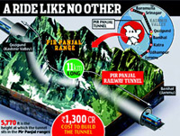
The 11.2 km long tunnel across the treacherous Pir Panjal mountain range, the boarder
of Jammu and the Kashmir Valley, is one of the key structures of this rail line
project and is the longest transportation tunnel in India and the second longest
in Asia. It is located between Banihal (Jammu) in the South and Qazigund (Kashmir)
in the North. The work on the tunnel began in November 2005 and about 1,300 workers,
150 engineers worked indefatigably overcoming all odds for the last seven years
to accomplish this engineering marvel.
The total stretch of 17·7 km section between Banihal and Qazigund was built
at a cost of Rs 16·9 bn, including Rs 13 bn for the 11170 meters ( 11.170
km) Pir Panjal tunnel, the longest on the Indian Railways network. This connects
the Jammu region to the 119 km Kashmir Valley line between Qazigund, Srinagar and
Baramula, which was completed ahead of the more difficult mountain section and opened
as an isolated route in stages during 2008-2009. The main tunnel of 11170 m length
includes a mined tunnel section of 10960 m length and Cut & Cover sections of
50 m in the south and 160 m in the north.
|
The Pir Panjal tunnel offers a year-round all-weather alternative to the 35 km road,
which is impassable in heavy snow. Built by Ircon International, Hindustan Construction
Corp and Geo-Consultants, it has five groups of five roof-mounted ventilation fans,
and safety systems including CCTV cameras every 62·5 m, fire detection and
hydrants every 125 m, emergency telephones every 250 m, alarms every 250 m, air
quality monitoring every 500 m, escape route signs every 50 m, emergency lighting
and a public address system. There is a 3·0 m wide road for rescue and maintenance,
along with a 772 m escape tunnel. The remaining 6·5 km of the route is in
cuttings up to 11·2 m deep or embankments 16·7 m high, with 39 bridges.
A 25 km extension from the IR railhead Udhampur to Katra is scheduled to open in
August, built at a cost of Rs10·3bn. The final 111 km connecting this to
the isolated Kashmir line is now
|

|
expected to be commissioned in 2017, including a 12 km tunnel and a 1 315 m long
and 359 m high bridge over the River Chenab.
The Geology
The Geology of the Pir Panjal mountain range includes the complete Cambro-Trias
Sequence and includes a mixture of very hard (UCS between 100 and 160 MPa) and moderately
to hard rock strata (UCS is between 40 and 80 MPa). Hard rock types include ande
site / basalt, quartzite, silicified limestone and agglomerates while the moderately
hard rock types include limestone, shale, agglomeratic shale and tuff. The C&C
tunnels and the mined portals are situated in fluvio-glacial sediments (soft ground)
which cover at both portals a length of more than 500 m of the mined tunnel section.
Table below shows predicted and encountered geological conditions in Pir Panjal
Tunnel location according to rock class and lengths.
The basic tectonic setting of Pir Panjal range in the area of tunnel alignment is
dominated by a folding structure leading to different dipping directions on both
sides of the range. The medium steep (60° to 70°) NE dipping of bedding
planes on the southern part become steeper towards the main range while on the northern
part flat to medium steep (35° to 40°) dipping towards SW is dominating.
The central areas show a distinct folding. Contact zones between rock units are
often faulted. Bedding of rock is striking sub perpendicular to tunnel axis.
Variable water conditions are expected. Joint aquifer, which will provide continuous
water inflow to the tunnel, is expected in the hard rock types and less seepage
water in the shale. High water inflow is expected in the fault zones, of which some
could be mapped and are predictable. Occurrence of extreme water inflow is possible
in karstic lime stone on the northern side of the tunnel. Actual cavities could
not be assessed or predicted and water encounter could be at any place. Particular
problems are expected for the shale section at the highest overburden where squeezing
rock and large deformations might occur.
|
The Challenge
Challenges were many but the Will to accomplish strong. In addition to the one of
its kind tunnel, the Rs 1,800-crore 240 Mw Uri hydroelectric project, situated very
close to the Line of Control or LoC, is also proposed to be completed at the earilest.
The horseshoe-shaped diversion tunnel, created for generating hydropower, will benefit
Uttarakhand, Uttar Pradesh, Haryana,
|
 |
Delhi and Chandigarh.
Drilling into the capricious rocks was not an easy task. At various points the technical
team encountered problems of seepage and softer topography which made the work difficult.
The tunnel project boasts of using technology never used before in India. The
New Australian Tunneling Method (NATM) was brought in for observing three-dimensional
movement of the rocks and avoiding collapses whenever weaker rock was being drilled.
The tunnel has also used ballast-less tracks, easier on maintenance.
A three-metre wide road runs alongside the track inside the tunnel as a safety measure
to keep the tunnel accessible under all circumstances. The walls are lined with
a water proofing membrane brought from Italy, keeping the all-weather tunnel dry.
The proximity of the dam to the LoC meant checks on movement of labour and officers
working on the project were stringent. Besides, for days together, all construction
work would come to a halt during the various stone pelting incidents during 2010
and after.
Both projects employed 2,700 labours together, working in three shifts through the
day. Skilled manpower has always been in short supply. Retaining them was another
problem, since workers would leave the site for other jobs like farming or return
to their villages when winter came. While snowfall during peak winter did not bring
construction to a complete halt, it drastically slowed activity Work also had to
be stopped during the Amaranth Yatra. Amid all this, getting the logistics in place
and keeping the smooth supply of raw materials was a major challenge.
Tunnel Design
The rapidly changing, very complex, Himalayan geology offers a great challenge to
any designer. The proposed construction method had to deal with varying ground conditions,
high over burden and large deformations. The complexity of the geology and limited
geotechnical information available under high overburden (1200 m) areas did not
encourage use of TBM. A new method of design had to be applied. The tunnel design
is based on NATM principle and assumes the ground around the tunnel to provide part
support without losing much of its inherent strength. The design approach had to
consider Flexibility in design, Employment of State-of-art materials and suitable
construction methodology.
The 8.4 meter wide, 7.3 meter high tunnel, designed for a life span of approximately
120 years, is almost straight from north to south. A 3m wide road runs along the
track for maintenance and emergency services. The height of the railway tunnel has
been kept 450m lower than that of the road tunnel so the effect of snow is minimal.
There is provision for ventilation, fire fighting and safety monitoring.
The designing had to consider removal of one million cubic metres of soil approximately
equivalent of one mountain using modern earth moving equipment, drilling and other
systematic blasting methods. The maximum overburden was 1,100m.
Electrification and elimination of maintenance requirement demanded a water proof
tunnel and it was decided to construct semi-dry tunnel. The water inflow is not
tolerated but locally wet patches can be accepted considering safety of the electrical
system to be installed. This tunnel has been designed in a modified Horseshoe shape
with 3 radius of curvature with excavated cross section varying from 48 m2to
80 m2 depending on the support class.
A 780m long access tunnel and a 50m deep shaft were also to be constructed for the
construction of the tunnel. These will be used as maintenance access and emergency
escapes. Waterproofing was completed for the whole tunnel by February 2011. Day-lighting
was achieved in October 2011.
Excavation Methods
Excavating tunnels through the geologically unstable rock of the seismically active
Pir Panjal range in the Himalayas requires a range of equipment and techniques.
In general three techniques were used namely-Excavation by Tunnel Excavator, Excavation
by Road header and thirdly, Excavation by drill and blast method. The use of Road
Header was one of the latest technologies being used on such a large scale in India.
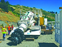
Road Header
The NATM Methodology
The tunnel has been constructed using New Austrian Tunnelling Method (NATM) and
it is for the first time such a method has been used on such a large scale in India.
“The New Austrian Tunneling Method (NATM) is based on a concept whereby the
ground (rock or soil) surrounding an underground opening becomes a load bearing
structural component through activation of a ring like body of supporting ground”.
Another recent definition on NATM given by Sauer (1988) states that NATM is: “…A
method of producing underground space by using all available means to develop the
maximum self-supporting capacity of the rock or soil itself to provide the stability
of the underground opening.”
In principle, following are a few important factors to be considered for NATM methodology.
- The inherent strength of the soil or rock around the tunnel domain
should be preserved and deliberately mobilised to the maximum extent possible.
- The mobilisation can be achieved by controlled deformation of
the ground. Excessive deformation which will result in loss of strength or high
surface settlements must be avoided.
- Initial and primary support systems consisting of systematic rock
bolting or anchoring and thin semi-flexible sprayed concrete lining are used to
achieve the particular purposes given above. Permanent support works are usually
carried out at a later stage.
- The closure of the ring should be adjusted with an appropriate
timing that can vary dependent on the soil or rock conditions.
- Laboratory tests and monitoring of the deformation of supports
and ground should be carried out.
- Those who are involved in the execution, design and supervising
of NATM construction must understand and accept the NATM approach and react co-operatively
on resolving any problems.
- The length of the unsupported span should be left as short as
possible.
All this is achieved by the application of an appropriately resistant initial support,
to preserve the rock mass strength and it should also accept the necessary deformation
and yet resist the loads. The initial lining is usually Shotcrete, steel lattice
girders and rock bolts either singly or in combination followed by secondary (permanent
lining).
Selection Criteria
Selection criteria whether to choose a TBM or NATM was extremely tricky in terms
of technology and expertise. Some of the important comparative factors which helped
the decision in favour of NATM are as under:
- TBM design requires reliable geologic information in the initial
stage itself and there is always likelihood of mixed-face excavation in Pir Panajal.
- There is also heterogeneous geology ie soil near portals to Trap
and quartzite in middle which is not well suited for TBM.
- Heavily faulted areas and/or wide fault zones are also expected,
TBM may be trapped by ground movement behind the face.
- High squeezing is anticipated in the middle zone with 1150m overburden
and likelihood of heavy water inflow in the lime stone zone with heavy over burden.
- High initial period needed for ordering, design, manufacture and
commissioning of TBM.
- Retrieval of TBM’s approaching each other requires large
cavern.
- TBM obstructs final lining activity for a long time after break-through.
- Non circular section can only be achieved by enlargement later.
- TBM requires specialized skilled crew and also there is heavy
requirement of electric power. There is a high risk of getting TBM stuck under squeezing
ground conditions, in fault zones and in alluvium like situation at the ends.
- Designing, tendering, manufacturing and installation of TBM takes
10 to 14 months. Therefore NATM method was selected for Pir Pnajal tunnel project.
- NATM can be adjusted to emerging ground conditions, flexibility
in terms of the excavation sequence and support measures.
- Excavation can be done with road header, drill and Blast.
- Maximum daily advance peaks of 10 m in stable rock conditions
can easily be targeted.
Main Tunnel
The main tunnel is a single track railway tunnel for operation
of passenger and freight trains and runs almost parallel to north – south
direction. On the left side of the track, looking towards increasing chainage, is
a motorable path of 3 m width which will be used for emergency and maintenance.
This road is directly accessible from both portals and the access tunnel. –
The tunnel is a mountain tunnel with an average elevation of approximately 1750
m and a maximal overburden of approximately 1100 m.
Access Tunnel
For an intermediate driving access an approx. 800 m long access tunnel with a downward
gradient of 10% will be constructed, intersecting the main tunnel at approx. 2.75
km from the south portal. The access tunnel shall be used to shorten construction
period of the main tunnel. During operation the access tunnel shall be used for
emergency and maintenance entrance and exit. If required it can be used also for
additional ventilation.
Access Shaft and Cross Passage
Another intermediate access is provided by a 55 m deep access shaft and an approximate
35 m long cross passage. With a second start of the main tunnel drive from the cross
passage, driving of the main tunnel towards south will be independent from the approx.
600 m long soft ground portion at the north portal and the effect of delays in this
section to the overall program.
Rock Classification
The geotechnical design uses a rock classification system of the Austrian Standard.
The result is the development of a rock mass model (geo-technical master plan):
Step 1: Determination of Rock Mass Types;
Step 2: Establishment of the Rock Mass Behavior Types;
Step 3: Excavation sequence and support is determined and described in different
Rock Class Types;
Step 4: Based on the results of steps 1 – 3 the alignment is divided into
sections with similar excavation and support requirements and the respective rock
class is allocated.
Tunnel Drainage & Waterproofing
|
As per contract requirement a “semidry” tunnel shall be designed where
local wet patches and dripping of water can be accepted. The drainage system includes
two side drainage pipes which can be omitted at dry tunnel sections, and a main
collector, which runs all along the tunnel. Seepage water collected in the side
drainage pipes and surface water from spill off or from dripping seepage water or
similar and collected throughout the tunnel in shallow ditches, will be conveyed
at regular distance to the main collector.
|
 |
Where required a real waterproofing system is installed between the primary (outer)
and secondary lining (inner) in the tunnel roof and the tunnel sidewalls. This will
be the case where water ingress over large areas occurs e.g. at karst sections and
heavily faulted and/or thinly bedded rock sections with seepage water. In addition
continuous water proofing will be installed along the soft ground sections at the
tunnel portals.
Award of Work to HCC
The work was awarded to Hindustan Construction Company Ltd (HCC), India’s
foremost infrastructure building company, which has immense tunnelling experience
in the toughest terrains, ranging from geologically complex
Himalayas to the soft soil of West Bengal. The total length of tunnelling work executed
by HCC is over 170 kilometers which covers all types of projects ranging from Hydro
Power, Transportation, MetroRail, Water Supply, Irrigation, and Sewerage. HCC implements
modern and efficient tunnelling technology that includes Tunnel Boring Machines,
NATM, Pneumatic shields and Gasket segments.
According to Mr. KG Tendulkar, Executive Director (Operations), Hindustan Construction,
“The construction of the railway tunnel through the Pir Panjal range forms
an integral part of the new railway line between Udhampur and Baramulla. The railway
line is expected to significantly boost trade and industry in the region and it
is a matter of pride for us to be involved in a significant new infrastructure initiative
of this nature.”
References
1. Construction of Pir Panjal Railway Tunnel - NATM experience
in the Himalayas, paper submission by- F. Prinzl,
V. Bhardwaj & A.H. Güvenc , GC-RITES-JV,
Gurgaon, India, A. Garg, RITES, Gurgaon,,India
2. Report from Yuvadesh News
3. Report from HindustanTimes
4. Report from Economic Times.
5. HCC Press Releasec
6. Pir Panjal by NATM Method by Ankur Jain, Dy.CE
7. NATM experience in Pir Panjal rail tunnel- Aishwarya Kumar,
Bhanu Prakash & Yogesh Velapure, IRCON.
Fact Sheet
|
Project
|
Pir Panjal Railway Tunnel T80
|
|
Type
|
Railway Tunnel
|
|
Location
|
Jammu & Kashmir, India
|
|
Client
|
IRCON International Ltd.
|
|
Consultants
|
GeoConsults - RITES joint venture
|
|
Time
|
2005 – 2013
|
|
Project Data
|
Single tracked, one tube;
Length- 10,960 m Cross section radius- 4,140 mm;
Excavation cross section - 70 m2
Access tunnel- approx.
800 m Access shaft- 50 m deep
Highest overburden of 1100 m
The total Excavation 11 lacks cum
|
|
Contractors
|
Hindustan Construction Company
|
|
Water Proofing
|
Tristar Global Infrastructure
|