Methods of Ground Improvement- An Overview
Large Civil Engineering Projects are being executed in all over the country in order to enhance the infrastructure of the country. Infrastructure facilities have to be often built at sites where the soil conditions are not ideal. To improve the strength of the soils, especially in case of granular type of soils, Compaction Methods are found as best methods among all type of techniques. Based on the mechanism applied for compacting the soil, it is sub divided into different methods like dynamic compaction, blasting, vibro techniques ...etc. When there are some limitations encountered for applying any of the above techniques, grouting techniques, stabilization of soil using different admixtures can be adopted effectively which can bring variations in the soil conditions. Several recent advancements in ground improving techniques using Geotextiles, Electric Treatment Methods are also being used at this juncture.
In a building structure, ground is evaluated for its bearing capacity, the capacity of the ground to bear the load. The ground can be improved to have a higher bearing capacity than what it has got in its original condition. To mitigate the failures, we need to improve the ground, it's important to improve the strength of the ground.
The natural property of the soil as it is exists at the ground is measured in California-bearing Ratio (CBR) to evaluate the mechanical strengths of road subgrades and base courses. For example, "In a road construction process, the structural thickness of the road contains Granular Sub base, bitumen layers that have to be designed. The thicknesses of these layers will depend on two factors namely CBR, weight and traffic of vehicles in that specific area. When the CBR is different in a single stretch, constructing the roads would be next to impossible. Consequently, we improve the ground to get a single and constant CBR value, which will be much higher than the original. It saves the cost of the upper layer and reduces the variations," adds Prof. Murthy.
There are several techniques that may be employed for Ground Improvement in isolation or in combination. They can be generally classified as under.
Ground Reinforcement
- Stone Columns / Lime Columns
- Soil Nails
- Micropiles
- Jet Grouting
- Ground Anchors
- Geosynthetics /Fibers
- Vibro-Concrete Columns
- Mechanically Stabilised Earth
- Mechanically Stabilised Earth
Ground Improvement
- Surface Compaction
- Drainage / Surcharge
- Electro-Osmosis
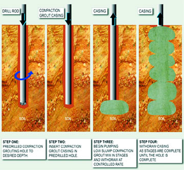
- Compaction Grouting
- Blasting
- Dynamic Compaction
Ground Treatment
- Soil Cements
- Lime Admixtures
- Flyash
- Dewatering
- Heating / Freezing
- Vitrification
Selection Criteria
Factors to be considered in selecting Soil Improvement Method can be epitomised as under;
-
The operational criteria for the facility; e.g. stability requirements, settlement criteria. These criteria establish the level of improvement required in terms of soil properties.
-
The area, depth, and total volume of soil to be treated
-
The soil type to be treated and its initial properties
-
Depth to groundwater table
-
Availability of materials, e.g., sand, water, admixtures, reinforcing elements.
-
Availability of specialized equipment and skilled labour force.
-
Construction and environmental factors; e.g., site accessibility and constraints, waste disposal, effects on adjacent facilities and structures.
-
Local experience and preferences; politics and tradition.
-
Time available
-
Cost; generally construction cost, but also life-cycle costs
-
Sustainability considerations; e.g., energy and carbon emissions.
QC/QA Procedures
-
Construction data records
-
Surface settlement & heave
-
Sampling and testing of treated soils
-
In situ testing (penetration & shear wave)
-
Pore pressure measurements
-
In situ hydraulic conductivity
-
Lateral movements
Performance of Improved Ground
-
Experience in use of well-established GI methods in "conventional" applications such as bearing capacity improvement, slope stabilization, pre compression and acceleration of consolidation, liquefaction mitigation and construction of seepage barriers has shown that the required performance can be obtained if the- Appropriate method is chosen for the problem and , the design and construction are done well
-
A common "trouble spot" is the difficulty in verifying that the desired level of improvement has been obtained, emphasizing again the need for a well-designed and implemented QC/QA program.
The following Table lists the category of improvement, the function and potential methods of ground improvement.
| CATEGORY |
FUNCTION |
METHODS |
COMMENT |
| Consolidation |
Accelerate consolidation,
increase shear
strength
|
1 Wick drains
2 Vacuum consolidation |
Viable for normally
consolidated clays.
Vacuum consolidation
viable for very soft clays.
Can achieve up to 90%
consolidation in a
few months.
|
| Load reduction |
Reduce load on
foundation, reduce
settlement |
1 Geofoam
2 Foamed concrete
3 Lightweight granular fills, tire chips, etc. |
Density varies form 1 kN/m3
to 12 kN/m3.
Granular fills usage subject
to local availability. |
| Densification |
Increase density,
bearing capacity,
and frictional strength of
granular soils. Decrease settlement and increase resistance to liquefaction
but is applicable for a
wider range of soils. |
1 Vibro-compaction using vibrators
2 Dynamic compaction by falling weight impact |
Vibrocompaction viable fo
clean sands with <15% fines. Dynamic compaction limited
to depths of about 10 m,
Both methods can densify
granular soils up to 80%
Relative Density.
Dynamic compaction
generates vibrations for a considerable lateral distance.
|
| Reinforcement |
Internally reinforces fills
and/or cuts. In soft
foundation soils, increases
shear strength, resistance to liquefaction and decreases compressibilit |
1 MSE retaining walls
2 Soil nailing walls
3 Stone column to reinforce foundations |
Soil nailing may not be
applicable in soft clays or
loose fills. Stone columns may be applicable in soft clay profiles to increase global shear strength and reduce settlement. |
|
Chemical stabilization
by deep mixing methods
|
Physio-chemical alteration
of foundation soils to
increase their tensile, compressive and shear
strength and to decrease settlement and/or provide lateral stability and or confinement |
1 Wet mixing methods using primarily cement
2 Dry mixing methods using lime-cement |
Applicable to soft to
medium stiff clays for
excavation support where
the groundwater table
must be maintained or for foundation support where
lateral restraint must be
provided or to increase
global stability and
decrease settlement.
Requires significant
QA/QC program for verification.
|
|
Chemical stabilization
by grouting
|
To form seepage cutoffs, fill voids, increase density,
increase tensile and compressive strength |
1 Permeation grouting with particulate or chemical grouts
2 Compaction grouting
3 Jet grouting, and
4 Bulk filling |
1 Permeation grouting to
increase shear strength or for seepage control,
2 compaction grouting for densification,
3 jet grouting to increase tensile and/or compressive strength of foundations, and
4 bulk filling of nay subsurface voids
|
| Load transfer |
Transfer load to deeper
bearing layer |
Column (pile) supported embankments on flexible geosynthetic |
Applicable for deep soft soil
profiles or where a tight
schedule must be maintained.
A variety of stiff or semi-stiff
piles can be used. |
| mats |
Table 1. Ground Improvement Categories, Functions, Methods and Applications (NHI, 2004)
Methods of Ground Improvement
The methods of ground improvement that can be adopted depend basically on nature of strata and purpose of improvement. Some of the commonly adopted methods are discussed here under.
1. Vertical Drains / Wick Drains
Vertical Drains are used to accelerate the consolidation of soft, low permeability soils. Drains are installed in a grid pattern designed to achieve the optimum time v. cost outcome. The most common forms of drain are strip or "Wick" drains and are introduced into the ground using a mandrel containing the drain material being installed into the soil. The mandrel is pushed to the design depth, where it releases the drain and is withdrawn leaving the drain in place. Menard Bachy has developed the use of small diameter circular plastic tube drains, which are more efficient than the flat "Wick" drains. These circular drains have particular application in the Vacuum Consolidation process.
 |
In the recent past, there has been number of different materials developed to replace the sand drains. These are basically flexible plastic sections having thickness varying from 5 to 10 mm and width from 100 to150 mm. The section has channels to permit flow of water. The perimeter of the section is covered with a layer of geo-textile to prevent the entry of soil particles into the channel. The advantage of such drain is that it results in minimum remoulding of surrounding soil during installation. The process of installation is also very fast. The machine is mounted on a crane and typical drain upto 10 m depth can be installed in a period varying from 1-2 minutes including the time for shifting the machine to the new location.
The percentage consolidation which can be achieved by such vertical drains can be theoretically predicted from the design charts developed based on theory of 3D consolidation. Typically, a deposit which requires a period of over ten years for 95% consolidation can complete the same consolidation within a short period of 3 to 6 months when vertical drains are installed.
2. Vacuum Consolidation
Vacuum Consolidation is an effective means for improvement of saturated soft soils. The soil site is covered with an airtight membrane and vacuum is created underneath it by using dual venture and vacuum pump. The technology can provide an equivalent pre-loading of about 4.5m high conventional surcharge fill. Vacuum-assisted consolidation preloads the soil by reducing the pore pressure while maintaining a constant total stress. Some of the applications are;
-
Replace standard pre - loading techniques eliminating the risk of failure.
-
Combine with a water pre-loading in scare fill area. The method is used to build large developments on thick compressible soil.
-
Combine with embankment pre-load using the increased stability
This is a soft ground improvement method which makes use of a prefabricated vertical drain (PVD) system. Using this method, a PVD is capped at the top and inserted into the soft seabed clay and vacuum suction is applied to reduce the atmospheric pressure so that the pore water pressure is reduced and the effective stress is increased accordingly. Since the placement of airtight sheeting on the surface to maintain air-tightness is not required, this method is far superior to conventional methods in terms of cost effectiveness and labour saving.
In vacuum dewatering technique also the layer is provided with vertical drains as mentioned above. The surface is then covered with a layer of sand blanket 150-300 mm thick and covered with a thin plastic sheet which is suitably anchored along the perimeter. Vacuum is then applied within the sand blanket which creates a suction pressure upto 50-60 mm height of mercury and forces the pore water out from the deposit through vertical drains. The area is also subjected to atmospheric pressure which then acts as a preload. The vacuum
pressure is maintained till the required improvement is achieved. The period of vacuum application can be predicted in similar way as discussed for the vertical drains.
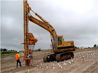
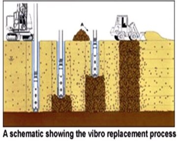
3. Vibro-Replacement Stone Columns
Vibro-Replacement extends the range of soils that can be improved by vibratory techniques to include cohesive soils. Reinforcement of the soil with compacted granular columns or “stone columns” is accomplished by the top-feed method.
Stone columns are cylindrical columns made below ground level which comprises of granular material of large size varying from 25 to 100 mm. A hole is made in the soft deposit by different techniques and then filled with stones in layers and compacted to form the complete column. When a structure is placed over the area treated by stone columns, majority of the load (80-90%) is transmitted to the stone column because of their higher stiffness. Balance 10-20% of the load is taken by clay deposit. With the help of this 10% of surcharge load, the soft clay is able to provide adequate confinement to the cylindrical column. The maximum permissible actual stress on the columns can be predicted from the known theory.
 |
The area treated by stone columns can be used to support only flexible structures such as embankment, oil storage tank, etc. because, the settlement even after treatment with stone column can be large (50-200 mm). Without stone columns the settlement could have been 3-4 times higher and also the bearing capacity would have been much less.
The stone columns are installed by different techniques, some of them are:
1. With bored piling equipment, a hole of required diameter is made with a steel liner. Stones are the poured in stage of 2-3 m height, compacted with a hammer at each level and the steel liner is simultaneously withdrawn as the height of column increases. This method does not create much lateral displacement within the soft clay, which can otherwise result in remoulding of the soil.
2. With a large size vibrator, a hole is formed in the ground using high pressure water jets. After vibrator is penetrated up to required depth of column, the stones are poured through the annular gap between the vibrator and surrounding soil. The high power vibration compacts the stones in stages. The stones are poured in stages and compacted till entire column is formed. This technique is called vibro-replacement.
3. In vibro-compaction, the vibrator is forced into the ground without water jets. The compaction is achieved by pushing soil particles to the surrounding soil. The vibrator is withdrawn in stages and the volume left by the vibrator is occupied by the surrounding soil. There is no necessity of stones to be added in this process. At the end of compaction, the surface settles to a small extent as a result of compaction. This technique is fast but suitable only for cohesionless deposits.
4. Rammed Column: In this technique, a steel liner with a closed end is pushed into the ground either with a drop hammer or with a vibratory hammer. After the liner penetrates the required depth, stones/sand is poured inside the liner (and the liner is gradually withdrawn keeping the liner under continuous vibrator or with light taping with the hammer).
Summary: Vibro Replacement
| Principle |
|
| Applicable soil(s) |
- Mixed deposits of clay, silt and sand
- Soft and ultra soft silts (slimes)
- Soft and ultra soft clays
- Garbage fills
|
| Effect(s) |
- Increased shear strength
- Increased stiffness
- Reduced liquefaction potential
|
| Common applications |
- Airport taxiways and runways
- Chemical plants
- Storage tanks & silos
- Pipelines
- Bridge abutments and approaches
- Offshore bridge abutments
- Road and railway embankments
|
| Maximum depth |
|
| Land / offshore application |
|
4. Lime Columns
Lime has been used widely in soil stabilisation for several years and in recent times quick lime has found wider application particularly in stabilisation of soil. Lime stabilisation is achieved by two ways depending on nature of soil (soft or desiccated), thickness of strata, depth of strata etc. Intrinsic mixing of lime with clay is generally resorted to, when the thickness of layer is small and is available at shallow depths; whereas lime column technique is adopted at locations where soft clay extends to larger depth. The lime reacts with soil and increases the strength and decreases the compressibility of soil. These reactions are hydration, cat-ion exchange, puzzolanic and carbonation. The substantial increase in strength, permeability and decrease in compressibility are mainly attributed to the formation of cementation products such as calcium silicate hydrate (CSH) and calcium aluminate hydrate (CAH) due to puzzolanic reaction.
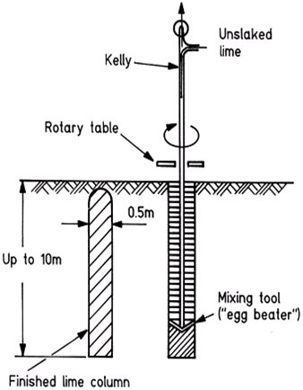 |
The lime columns are formed insitu by mixing the soil insitu with unslaked lime using an auger, shaped like a giant eggbeater (Figure 9). Normally quick lime is added up to 10% of dry weight of soil. The rotation rate is 60 rpm, when the tool is pushed down into the soil corresponding to pitch of the inclined blades. At the required column length, the rotation is reversed and the tool is withdrawn gradually. While withdrawing the auger the lime is forced into the soil through a hole in the auger using compressed air. The auger is withdrawn slowly in order to mix the lime thoroughly with the soil and to compact the lime-soil mixture. The amount of lime forced into the soil is recorded as well as the injection pressure. This equipment has a capacity to form 10m long lime column of 0.5m diameter in about 10 minutes.
The increase in strength of lime treated soil increases with time. One third of final strength can be achieved within a month of stabilisation. The fifty percent of final strength can be achieved in one year after the installation of lime column. The reaction of lime with clay is similar to concrete which also exhibits strength increase with time. The full strength of lime treated ground can be achieved after several years of installation.
5. In-situ Deep Mixing
In-situ deep mixing using hydraulically operated helical blade augers penetrates the ground to the required depth. The hollow stem of the auger is used to inject cement slurry/lime/any other stabilising compound into the ground. A pair of 2 or 3 augers is operated simultaneously. After injecting the stabiliser into the ground, the augers are rotated such that the soil along with the stabiliser is churned in-situ and mixed the stabiliser thoroughly with the soil without necessity of taking out the soil. The auger configuration can be chosen such that either a stabilised wall can be formed (to act as barrier) or the entire area can be stabilised.
Advantages
- Construction of overlapping soil-cement columns (in-ground shear walls)
- Reduces earthquake-induced shear strains of treated zones
- Increases composite shear strength of treated zones
- Prevents migration of excess pore between untreated and treated zones
- Works well in high fines soil (large applicability range)
Disadvantages
- Requires overhead clearance
- Stiff strata can impede augers
- Inefficient for liquefiable soils with a limited thickness at a significant depth
- Overlapping soil-cement columns are brittle = tendency to crack with earthquake shaking
6. Thermal Treatment
In thermal treatment, the moisture from the soft clay is driven out by raising the temperature of the deposit. This is done by passing hot gasses through the soil. Inclined bore holes of suitable diameter are drilled along the slope and a fire is created near the bottom of the holes. The bore holes act as a chimney and carry the hot flues. This reduces the water content considerably and stabilises the slope. The deposit could also be heated by electrical energy, but it works out to be more expensive. Thermal treatment is used more for temporary purpose like stabilisation of excavation slope during construction.
7. Compaction Piles
Compaction of soil is the process by which the solid soil particles are packed more closely together by mechanical means, thus increasing the dry density. It is achieved through the reduction of the air voids in the soil, with little or no reduction in the water content. This process must not be confused with consolidation, in which water is squeezed out under the action of a static load. The air voids cannot be eliminated altogether by compaction, but with proper control they can be reduced to a minimum.
In olden days, compaction piles comprised of wooden tree trunks were driven into ground at required spacing. The voids in the strata gets reduced equivalent to the volume of the pile. The spacing between the piles can be chosen to achieve the required improvement. There has been considerable development in installing sand compaction piles in which a casing pipe with closed end is driven to the required depth, filled with coarse sand in layers and the pipe is withdrawn compacting the sand. Installation of compaction pile is very fast and effective in compacting the cohesionless deposits. The technique is not suitable for cohesive soil as the lateral displacement while driving the pile can result in remoulding of surrounding soil.
8. Roller Compaction
The degree of compaction achieved in the field by a roller will depend on several factors including -Thickness of lift, Area over which the pressure is applied, Intensity of pressure applied to the soil, Type of roller and Number of roller passes. Two types of rollers namely; Static and Vibratory types are used to achieve shallow compaction. Examples of Static rollers are;
-
Smooth surface rollers
-
Sheepsfoot rollers
-
Grid rollers
Examples of Vibratory rollers are;
-
Plate Compactors
-
Vibro Rammers
-
Impact Rollers
-
Vibratory Rollers
Figure: Sheepsfoot Roller
Figure: Impact Roller
Figure: Smooth Wheel Roller
Figure: Pneumatic Rollers
Vibratory rollers are particularly useful for compacting granular soils. Self propelled and towed vibratory roller of various sizes, weights, and vibration frequencies are available. The vibrations are generally produced by rotating an off-centre weight. Vertical vibrations can be obtained by using two synchronized counter-rotating weights. For field compaction work, the specification requires that the granular soil be compacted to a certain minimum relative density at all depths. Determination of the height of each lift depends on the type of roller and the economic number of passes.
9. Vibroflotation
Vibro-flotation is a technique for in situ densification of thick layers of loose granular soil deposits. It was developed in Germany in the 1930s. The first Vibroflotation device was used in the United States about 10 years later. The process involves the use of a Vibroflot (also called the vibrating unit), which is about 2.1m (~7ft) long. This vibrating unit has an eccentric weight inside it and can develop a centrifugal force, which enables the vibrating unit to vibrate horizontally. There are openings at the bottom and top of the vibrating unit for water jets. The vibrating unit is attached to a follow –up pipe. Figure 13 shows the entire assembly of equipment necessary for conducting the field compaction. The entire Vibroflotation compaction process in the field can be divided into four stages.
Figure: Typical cross section of Vibroflot
-
The jet at the bottom of the Vibroflot is turned on and lowered into the ground
-
The water jet creates a quick condition in the soil and it allows the vibrating unit to sink into the ground
-
Granular material is poured from the top of the hole. The water from the lower jet is transferred to the jet at the top of the vibrating unit. This water carries the granular material down the hole.
-
The vibrating unit is gradually raised in about 0.3 m (=1 ft) lifts and held vibrating for about 30 seconds at each lift. This process compact the soil to the desired unit weight.
10. Dynamic Compaction
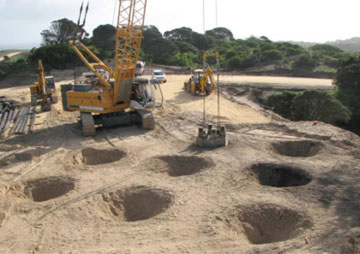 |
The impact on the ground transmits compression waves, which spreads radially from the point of impact. The compression waves travel fast and creates liquefaction of the strata, which is saturated. It is followed by shear waves, which has less velocity but higher energy. The shear wave reorients the soil particles, which are liquefied state to denser state and compacts the configuration. Representative blows (5-10) are applied at each treatment point. The spacing between the treatment point, number of impact at each point, etc. can be varied depending on the required improvement. There is no rational theory to arrive at spacing and usually it is decided by compacting a trial area. Deposits upto 10-20 m depth can be successfully compacted by this technique. Wherever the silt/clay content in deposit exceeds 15 to 20%, the method is found to be less effective. After each blow, the pore pressure developed in the ground takes long time to dissipate as its percentage fines is higher. Though the technique is used in deposits such as clayey sand and silty sand, the efficiency is less compared to compaction of sand without fines.
Dynamic compaction is a technique used for the densification of granular soil deposits. This process consists primarily of dropping a heavy weight repeatedly on the ground at regular intervals. The weight of the hammer used varies between 10 to 150 tons dropped from a height varying from 8 and 40 m. These stress waves generated by the hammer drop help in achieving the desired densification. The centre to centre distance between the drop points is a function dependant on the depth of compressible layer; deeper layers are compacted with wider spacing and shallow depths are with closer spacing. Craters formed due to the drops are replenished with sand after each drop as indicated in the figure. The degree of compaction achieved at a given site depends on the following three factors:
11. Deep Blasting Method
Thick cohesionless deposits such as mine back fill or natural cohesionless deposit can be effectively densified by deep blast. In this technique, a bore hole is made to a depth approximately 3/4 or 2/3 of the total depth. Suitable explosive is lowered to the bottom of the borehole and the space above is back filled with compacted soil (known as stemming). The explosive is attached with cordex which is taken upto the surface and connected to electric detonator. When the explosive is detonated, it creates a cavity, which expands instantaneously. The cavity expansion generates shock waves. Propagation of these waves densifies the soil to certain extent.
After the blast, a large conical depression is observed at the place of blast. The water within the pores of the deposit gets expelled out and comes up to the ground and forms a large pool of water in the cone of depression. The quantity of charge and spacing between explosives can be suitably selected to achieve the required densification. As a thumb rule, about 15 to 45 grams of explosive is required for densification of every m3 of the deposit. Initial loose deposit which has relative density of about 50% and susceptible to liquefaction can be densified to a relative density of over 60% which is adequate to prevent liquefaction. The vibrations created during the blast are within permissible limits for construction purpose.
12. Jet Grouting
High pressure injection grouting technique have been developed which are capable of injecting grout even in less permeable soil like clayey soil. A fluid stream of high energy is produced by a nozzle at lower end of the drill rod which cut into the surrounding soil. Usually the stream consists of water or sand suspension. Grout columns are formed by continuously turning and retracting the drill rod. The diameter of columns depends on the pressure adopted and permeability of the surrounding soil. Typical application of ground improvement by grouting is to strengthen the existing foundation, supporting tunnel roof, trench excavation in weak soil, create barrier for contaminated soil, cut-off trench for reducing seepage loss, etc.
 |
Grouting selection considerations are Site specific requirement, Soil type, Soil grout ability, Porosity. Grouting can be prevented by Collapse of granular soils, Settlement under adjacent foundations, Utilities damage, Day lighting. Grouting can provide increased soil strength and rigidity, reduced ground movement, Predictable degree of improvement.
Jet grouting is a general term used by grouting contractors to describe various construction techniques used for ground modification or ground improvement. Grouting contractors use ultra high-pressure fluids or binders that are injected into the soils at high velocities. These binders break up the soil structure completely and mix the soil particles in-situ to create a homogeneous mass, which in turn solidifies. This ground modification / ground improvement of the soil plays an important role in the fields of foundation stability, particularly in the treatment of load bearing soils under new and existing buildings; in the in-depth impermeabilization of water bearing soils; in tunnel construction; and to mitigate the movement of impacted soils and groundwater.
Advantages
- Construction of overlapping soil-cement columns (in-ground shear walls)
- Reduces earthquake-induced shear strains of treated zones
- Increases composite shear strength of treated zones
- Prevents migration of excess pore between untreated and treated zones
- Works well in low overhead
- Can target specific depth interval
- Works well in high fines soil (large applicability range)
Disadvantages
- Hydraulic fracture
- Overlapping soil-cement columns are brittle = tendency to crack with earthquake shaking.
Conclusion
The ground improvement techniques as the technology advances are becoming more and more sophisticated. Quality Control and Quality Assurance together with computer aided analyses are helping to arrive at accurate understanding of ground deformations. Innovations in the field may be further be expected in the future along with the emerging new needs from the construction site and feedback from experts.
References
- Lecture by Prof. G L Sivakumar Babu, IISc, Bangalore
- Ground improvement techniques - an overview; Dr.S.R. Gandhi, IIT Madras
- Shallow and deep compaction for made-up and in-situ soils; Dr. V.K. Stalin- Assistant Professor, Department of Civil Engineering, Anna University Chennai.
- Ground Improvement- Scdot Geotechnical Design Manual
- NYSDOT Geotechnical Design Manual
- IMPROCE 2009
- Presentation on Study of Ground Improvement Techniques with an Emphasis on Deep Soil Mixing by Prof. Payum Vossoughi