Roller Compacted Concrete- RCC
And a Case Study- Ghatghar Dam Project
Bharathi Ganesh, Dr. H. Sharada Bai
Concrete is an important construction material since Roman times [the Colosseum
is largely built of concrete and the concrete dome of the Roman Pantheon is the
world's largest non-reinforced concrete Dome structure). Its appeal has endured
for a number of reasons, not least its compressive strength and resilience to weather
and fire but to its adaptability in creating a structure sound in every respect,
changing the design and construction world completely.
Recent innovations in concrete have further improved concrete’s credentials
in terms of its material consumption, overall cost per unit volume, duration of
construction required, performance, aestheticism, applicability, adaptability to
the site requirements, environmental friendly, sustainability [with the use
of industrial waste as alternative constituent in it], and so on. Many
new technologies are changing the way we build and what we build with concrete.
These developments in concrete have taken the construction industry by storm.
With the explosive growth in the infrastructure industry, another development in
1970 that has led to more creative use of concrete suiting to the requirements of
the site, to make the construction faster, is Roller Compacted Concrete [‘RCC’
for this article].
Definition
|
Definition - ACI 207.5R-89 defines Roller Compacted Concrete (RCC) as concrete compacted
by roller compaction. The concrete mixture in its unhardened state must support
a roller while being compacted [using a roller, often a vibrating roller].Thus RCC
differs from conventional concrete principally in its consistency requirement. For
effective consolidation, the concrete mixture must be dry enough to prevent sinking
of the vibratory roller equipment but wet enough to
|
 |
permit adequate distribution
of the binder mortar in concrete during the mixing and vibratory compaction
operations.
The Genesis
Roller Compacted Concrete (RCC) got its start in the Seventies [1970], when the
Canadian logging industry switched to environmentally cleaner, land-based log-sorting
methods. The industry needed a strong pavement to stand up to massive loads and
specialized equipment. Yet economy was equally important: log-sorting yards that
can span 40 acres (16 hectares) or more. Roller Compacted Concrete met these challenges
and has since expanded to other heavy - duty applications.
Applications
Applications of Roller Compacted Concrete on other types of construction were developed
in the 1980s. Its primary use to date has been in new dam construction and
the rehabilitation of existing dams. It has also been used for paving areas that
receive heavy axle loads and has had limited use in road construction. Following
are some of the structures constructed using Roller Compacted Concrete (RCC)
-
In 1986, Gears, Inc. was the contractor on one of the first RCC dam rehabilitations.
-
Spring Creek Dam was the highest dam in the world to be rehabilitated using this
economically attractive and environmentally pleasing solution. It was nominated
for the Civil Engineering project of the year.
- New Application used along the Interstate-285 [an
Interstate Highway loop encircling
Atlanta, Georgia, for 63.98 miles or 102.97 km] shoulder
repaving project is doing more than reconstructing the roadway's shoulders with
6 inches of RCC, making a history.
- North of I-20, 16-in.-thick sections of existing pavement are
being removed and replaced with 8 in. of graded aggregate topped with 8 in. of RCC,
anticipating possible future use of the shoulder as a traffic lane.
- The Tennessee Valley Authority used 8,000 cu. yards of RCC as
structural fill to support the turbine-building slab at the Bellefonte Nuclear Power
Plant in Scottsboro, Ala.
- In 1980, the Ocoee No. 2 Dam in Ocoee, Tenn., was the first use
of RCC for overtopping protection.
- In 2001, Honda chose RCC for more than 100 acres of pavement for
its new car-manufacturing plant in Lincoln, Ala.
-
The Southeast Cement Association has recently been pitching RCC as a product that
is appropriate for smaller projects. Industrial park roads, small-scale site paving
and residential projects can all be candidates for RCC.
|
|
The facility General Motors' Saturn manufacturing plant in
Spring Hill, Tenn, built by Georgia Dept. of Transportation [GDOT] is the largest
RCC pavement project ever built, encompassing 134 acres of plant roads, vehicle
storage yards and delivery areas.
Performance
Roller Compacted Concrete may be used in lieu of conventionally
placed concrete in concrete gravity and arch-gravity dams. RCC can be placed as
quickly as possible and its operations include as little manpower as possible.
RCC structures have been designed for a wide range of performance conditions, from
low-strength more massive structures to high-strength less massive structures.
RCC has started its specialized applications in mainstream pavements such as Port,
intermodal, and military facilities; parking, storage, and staging areas, streets,
intersections, and low-speed roads. Now, RCC is used for any type of industrial
or heavy-duty pavement. The reason is that it has the strength and performance of
conventional concrete with the economy and simplicity of asphalt. Coupled with long
service life and minimal maintenance, RCC's low initial cost adds up to economy
and value.
The main characteristics like high strength, long-term durability and cost-effectiveness
make RCC simple, fast, and economical. Roller Compacted Concrete
pavements eliminate common and costly problems traditionally associated with asphalt
pavements.
RCC pavements
Roller Compacted Concrete pavements generally exhibit following characteristics;
- Resist rutting
- Span soft localized sub-grades
- Will not deform under heavy, concentrated loads
- Do not deteriorate from spills of fuels and hydraulic fluids
- Will not soften under high temperatures.
- When appearance is important, joints can be saw cut into the RCC
to control crack location. If economy outweighs appearance, the RCC is allowed to
crack naturally.
- The strength to withstand heavy and specialized loads; the durability
to resist freeze-thaw damage; and the versatility to take on a wide variety of paving
applications from container ports to parking lots makes RCC the right choice for
tough duty.
The main features of RCC with its benefits are summarized in Table 1
Cost Reduction
The reduction in overall cost of the project and hence reduction in the construction
times is due to the following points.
- Cement consumption is lower because much leaner concrete mixtures
can be used.
- Formwork costs are lower because of the layer placement method.
- Pipe cooling is unnecessary because of the low temperature rise.
[Use of Fly Ash].
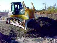
- Cost of transporting, placement, and compaction of concrete is
lower because concrete can be hauled by end dump trucks; spread by bulldozers and
compacted by vibratory rollers.
Rapid construction techniques (compared with those for concrete and embankment dams),
reduced material quantities, very high production rates possible in construction
reduce administration costs directly. It also helps in achieving earlier project
benefits, possible reduction or deletion of diversion facilities and possible use
of dam sites with limited construction seasons.
The shorter base dimension of an RCC dam, compared with that of an embankment dam,
reduces the required size and length of the conduit and penstock for outlet and
hydropower works and also reduces foundation preparation costs.
An embankment dam with a separate spillway and outlet works is generally more costly
than the RCC dam with an integral spillway and outlet works. The cost of an RCC
dam intake is considerably lower than the cost of an intake structure for an embankment
dam, especially in high seismic areas.
Table 1 – Features and Benefits of RCC
|
Features
|
Benefits
|
|
High compressive strength (4,000 to 10,000 psi) (28 MPa to
69 MPa)
|
Withstands high concentrated loads and impacts from heavy industrial, military,
and mining applications.
|
|
High flexural strength
(500 to 1000 psi) (3.5 MPa to 7.0 MPa)
|
Supports heavy, repetitive loads without failure and spans localized soft
subgrade areas, which reduces maintenance costs and down time.
|
|
Modulus of Elasticity
|
6.9 GPa at one day, [21 – 38] GPa at 28days and [30-47]GPa at one year.
|
|
Poisson’s Ratio
|
Typically ranges from 0.15 – 0.22
|
|
High Shear Strength
|
Eliminates rutting and subsequent repairs.
|
|
High Density, Low Absorption
|
Provides excellent durability, even under freeze-thaw conditions; eliminates
seepage through pavement. Density ranges from [2240-2560] kg/m3.
|
|
Low Water Content,Low water/cement Ratio
|
Increases strength, reduces permeability, and enhances durability and resistance
to chemical attack.
|
|
Very Good Aggregate interlock
|
Provides high shear resistance at joints and uncontrolled cracks to prevent
vertical displacement or faulting.
|
|
No steel reinforcing or dowels except under special circumstances
|
Speeds and simplifies construction, reduces costs.
|
|
No forms or finishing
|
Speeds construction, reduces cost, minimizes labour.
|
|
No formed or sawed joints
|
Speeds construction, reduces cost. (To enhance appearance, joints can be sawn into
RCC pavement.)
|
|
Hard, durable, light-coloured surface
|
Resists abrasion, eliminates need for surface course and reduces cost. The light
color reduces lighting requirements for parking and storage areas.
|
Limitations
Some of the limitations of RCC constructions are;
- Aesthetics - RCC does not have the
same appearance as other types of concrete. It is not as pretty and smooth as regular
concrete.
- Rougher Surface Texture - The mix
design and construction methods create a surface texture that gives it a characteristic
coarse finish.
- Limited to Low-Speed Traffic - Due
to the nature of its surface, RCC is not appropriate for all types of traffic. Vehicles
travelling at high speeds would experience a little bumpy ride. That makes it better
for applications where strength and durability are needed instead of speed. This
part of RCC technology is being addressed with newer technologies and pavement topping
techniques to provide smooth surface of the roads.
Material Requirement
Material selected for RCC and designed mix should be such that
RCC must maintain a consistency that will support and be suitable for a vibratory
roller and haul vehicles or other external methods. Much of the guidance on materials
provided in ACI 207.1R (Mass Concrete) may be applied to RCC.
Cement & Cementitious Material
|
Cement & Cementitious Material
Roller Compacted Concrete (RCC), can be made
with any of the basic types of Portland Cement. The cementitious material content
for RCC dams has varied over a broad range from 100 lb/yd3 (59 kg/m3)
to more than 500 lb/yd3 (297 kg/m3). Typically bedding mixtures
contain [360 to 460] kg/m3 of cement, and [170 – 220] kg/m3
of Fly Ash.
|
 |
An essential element in the proportioning of RCC for dams is the amount of paste.
The paste volume must fill or nearly fill aggregate voids and produce a compactable,
dense concrete mixture. The paste volume should also be sufficient to produce bond
and water-tightness at the horizontal lift joints, when the mixture is placed and
compacted quickly on a reasonably fresh joint. Experiences have shown that mixtures
containing a low quantity of cementitious materials may require added quantities
of non-plastic fines to supplement the paste fraction in filling aggregate voids.
Pozzolans
Use of Pozzolans in RCC mixtures may serve one or more of the following purposes:
1) as a partial replacement for cement to reduce heat generation; 2) as a partial
replacement for cement to reduce cost; and 3) as an additive to provide supplemental
fines for mixture workability and paste volume. The rate of cement replacement may
vary from none to 80 percent, by mass.
The selection of a Pozzolan suitable for RCC should be based on its conformance
with ASTM C 618. Class F and Class N Pozzolans are usually preferred, since they
normally contribute less heat of hydration than Class C and have greater sulphate
resistance.
Aggregates
The aggregates for RCC projects have to be been constructed with aggregates meeting
all the ASTM C 33 requirements, with the exception of an increased amount of fines
passing the No. 200 (0.075 mm) sieve. The American Concrete Institute (ACI) has
established aggregate gradation limits that have produced quality RCC pavement mixtures
[Figure 1 & Table 2].
Coarse aggregates
Consist of crushed or uncrushed gravel or crushed
stone while the fine aggregates consist of natural sand, manufactured sand, or a
combination of the two. Crushed aggregates typically work better in RCC mixes due
to the sharp interlocking edges of the particles, which help to reduce segregation,
provide higher strengths, and better aggregate interlock at joints and cracks. Because
approximately 80 percent of the volume of a high-quality RCC mix is comprised of
coarse and fine aggregates, they should be evaluated as to their durability through
standard physical property testing such as those outlined in ASTM C 33.
However, in RCC mixtures, the potential for segregation and the means of compaction
must also be primary considerations in selecting the maximum size of aggregate.
Early projects in the U.S. used a 3 in. (75 mm) nominal maximum size aggregate (NMSA);
however, a 2 in. (50 mm) NMSA is less prone to segregation and is becoming more
widely used.
The combined aggregate gradation should be selected to minimize segregation. A good
compactable RCC mixture is having a grading that is consistent and contains more
material passing the No. 4 (4.75 mm) sieve than typical in conventional concrete
of similar nominal maximum size aggregate. Gap-graded mixes that are dominated by
two or three aggregate sizes are not desirable for RCC.
Fine Aggregate / Fines
In low-cementitious materials content mixtures, supplemental fines, material passing
the No. 200 (0.075 mm) sieve, are usually required to fill all the aggregate void
spaces. Depending on the volume of cementitious material the fines may be 8 to 12%
of total solids by volume, or 12 to 16% by mass. Characteristics of the fines and
fines content will affect the relative compactability of the RCC mixture and can
influence the number of passes of a vibratory roller required for full compaction
of a given layer thickness. However, these fines need to be non-plastic with their
Plasticity Index (PI) not to exceed 4.
Chemical admixtures
Chemical admixtures have been effective in RCC mixtures that contain sufficient
water to provide a more fluid paste. ASTM C 494, Types A (water reducing) and D
(water-reducing and retarding) are the most commonly used chemical admixtures. Air-entraining
admixtures are not commonly used in RCC mixtures because of the difficulty in generating
the air bubbles of the proper size and distribution when the mixture has a no-slump
consistency.
|
Sieve Size
|
Percent Passing
|
|
Inch
|
Millimeter
|
Minimum
|
Maximum
|
|
3/4"
|
19.000
|
100
|
100
|
|
1/2"
|
12.500
|
70
|
90
|
|
3/8”
|
9.500
|
60
|
85
|
|
#4
|
4.750
|
40
|
60
|
|
#8
|
2.360
|
35
|
55
|
|
#16
|
1.180
|
20
|
40
|
|
#30
|
0.600
|
15
|
35
|
|
#50
|
0.300
|
8
|
20
|
|
#100
|
0.150
|
6
|
18
|
|
#200
|
0.075
|
2
|
8
|
Fig. 1 – Gradation
of CA for RCC
Reinforcement
It becomes necessary at times to embed reinforcing steel in RCC for the purpose
of anchoring various structural features. These structural features could be outlet
works structures, training walls for spillways, parapets, etc.
The reinforcement in the form of heavy welded wire mats provided in the RCC placement
will help to:
- Prevent the formation of wide cracks that might make the RCC susceptible
to deep abrasion-erosion from ash-laden flood flows,
- Provide bending resistance to limit cracking due to differential
settlement, and
- Provide shear-friction resistance across cracks to prevent blocks
of RCC, formed by perimeter cracking, from being dislodged by flood waters.
Mix Design
|
There currently exists several methods for proportioning RCC mixes for pavements;
however, there is not one commonly accepted method. The main RCC proportioning methods
include those based on concrete consistency testing, the solid suspension model,
the optimal paste volume method, and soil compaction testing. Whichever method is
employed, the goal is to produce an RCC mixture that has sufficient paste volume
to coat the aggregates in the mix and to fill in the voids between them. Regardless
of which
|
|
proportioning method is used, it is important that an RCC mixture meet the following
requirements:The fine and coarse aggregates should be chosen to achieve the required
density and to provide for a smooth, tight surface
- The moisture content should be such that the mix is dry enough
to support the weight of a vibratory roller yet wet enough to ensure an even distribution
of the cement paste
- The cementitious materials used should meet the required design
strength requirements at minimal cost with sufficient paste volume.
Selecting Mix Proportions
Procedure for Selecting RCC Mixture Proportions- Special concrete properties, such
as stress-strain characteristics, thermal properties, creep, etc., should be considered
during the material selection process and ultimately evaluated after the concrete
proportions are established. A comprehensive laboratory test program would normally
include a series of mixtures spanning the specified strength requirements with specialized
tests on selected mixtures in order to provide a comprehensive evaluation of the
materials.
|
Requirements
The requirements related to the properties of the RCC mixture are:
- Required/specified strength and age
- Expected exposure time and condition
-
Cementitious materials limitations and admixture requirements
-
Maximum size, source, and quality of aggregate,.
The mixture proportioning procedure is adopted as per the methods given in ACI 207.5R-99
based on the assumption that the concrete materials are suitable for the intended
use. For structural applications, the required average compressive strength (fcr)
should be determined using procedures described in EM 1110-2-2000 or ACI 214. However,
for normal mass concrete applications, these procedures may be somewhat overly conservative,
and a modified approach to establishing an over design factor and the required average
strength may be considered.
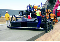
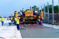
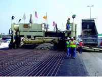
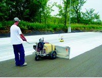
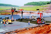
Process
RCC owes much of its economy to high-volume, high-speed construction methods. Large-capacity
mixers set the pace. Normally, RCC is blended in continuous-mixing pug mills at
or near the construction site. These high-output pug mills have the mixing efficiency
needed to evenly disperse the relatively small amount of water used. Dump trucks
transport the RCC and discharge it into an asphalt paver, which places the material
in layers up to 10 inches (250 mm) thick and 42 feet (13 m) wide.
When placing RCC during hot weather, it will be to the contractor’s advantage
to keep the concrete as cool as possible during
|

|
placement and compaction. As ambient air temperature increases beyond 90 degrees
F, the time allowed from time of mixing to completion of compaction should be reduced
accordingly (for example, from 60 minutes to 30 to 45 minutes). To compensate for
moisture loss during hauling and placement, additional mix water can be added at
the plant. For long haul times, consideration should be given to the use of hydration-stabilizing
admixtures to provide more workability time.
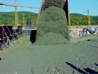
Compaction
Compaction begins immediately after placement and continues until the pavement meets
density requirements. There are two factors that should be considered when evaluating
hot-weather construction of RCC pavements: ultimate strength and workability.
Workability
Hot temperatures will make the concrete less workable and more difficult to place
and compact, resulting in a poorer quality final product. High temperatures lead
to higher rates of moisture evaporation, which is very important to monitor with
RCC because there is so little moisture in the concrete. As temperatures increase
from 700 F to 900 F[21.110C to32.220C]
the time to initial set and final set are reduced by 20 to 30 percent.
Curing of RCC
|
The optimal curing temperature for concrete is from 500 F to 700
F[17.780C – 21.110C]. When concrete is cured at temperatures
above 800F [23.330C] the early strengths (1, 3, 7 days) are
higher than concrete cured at normal temperatures. However, ultimate strength is
reduced 5 to 15 percent, if RCC is cured at 900F to 1050F
[32.220C to 37.220C] compared to curing at 730
F.
Construction specifications for RCC dams often require that the concrete mix temperature
not exceed 800 F. As with conventional concrete, curing is very important
for RCC. However, RCC has no bleed water, so the main concern is drying. At least
three negative things will happen if RCC is allowed to dry:
- The concrete will experience drying shrinkage which will lead
to cracking,
-
The cement will not continue to hydrate which will result in lower strengths and
less durability, especially at the surface, and
|
|
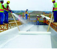
To keep RCC from drying the surface should be kept moist for 7 days or until a curing
compound is applied. The surface should be gently moistened with water from the
time compaction is complete. Curing compounds conforming to ASTM C 309 which are
used for conventional concrete can be used for RCC. However, because RCC has a more
open texture surface than conventional concrete, the curing compound application
rates are 1.5 to 2 times the application rates used for conventional concrete.
Effect of Temperature
Since heat of hydration is not a concern with RCC pavements, a better approach to
reduce the temperature of the concrete mix is to cool the coarse aggregate either
by shading the aggregate piles or sprinkling the piles with water. The water sprinkling
approach also aids in the mixing operation by providing moist aggregate which helps
assure a more uniform, consistent mixture.
Performance Evaluation of RCC
Properties important to the seismic analysis of RCC dams include compressive strength,
tensile strength, shear strength, modulus of elasticity, Poisson's ratio, and density.
Except for density, all these properties are strain-rate sensitive, and the strain
rates that occur during major earthquakes are on the order of 1,000 times greater
than those used in standard laboratory testing.
Properties
The properties of hardened RCC are similar to those of conventionally placed Mass
Concrete (CMC). Some properties will be determined by laboratory testing and some
will be assigned by the engineers. Some properties, like modulus of elasticity,
creep, and, to some degree, tensile strain capacity, are difficult to estimate without
testing.
Strength and Elastic Properties
The strength and elastic properties of RCC vary depending on the mixture components
and mix proportions in much the same manner as for CMC. Aggregate quality and cementitious
content are the principal factors affecting strength and elastic properties, but
these properties may be as much dependent on field control of mixing and placing
operations as on mixture ingredients or mixture proportions.
Compressive Strength
Common RCC mixtures may produce compressive strength ranging from 6.9 MPa (1000
psi) to over 27.6 MPa (4000 psi) at 1-year age. Most RCC projects have used mixtures
producing an average compressive strength between 13.8 and 20.7 MPa (2000 to 3000
psi) at 90-days to 1-year age.
Tensile Strength
Tensile strength can be measured by several methods, including the direct tension
method (CRD-C 164), the splitting tensile method (ASTM C 496), and the flexural
test or modulus of rupture method (ASTM C 78). The tensile strength is more dependent
on aggregate bond than compressive strength, hence the relationship between the
tensile strength and the compressive strength of concrete not only varies with the
method of test, but also varies with the type and maximum size of aggregate.
Direct Tensile Strength
Direct tension test results for RCC, similar to those for CMC, are lower than for
splitting tensile tests (often about 25 to 30 percent lower than splitting tensile
strength), The parent direct tensile strengths from a number of projects, using
both cores and cylinders, have ranged from 3 to 9 percent of the compressive strength,
with most values between 6 and 8 percent. If test strengths are based on wet-screening
and removal of aggregates larger than 38 mm (1.5 in.), test values for the full
mixture should be reduced by 10 percent.
Flexural Strength
Flexural strength, or modulus of rupture, is a measure of tensile strength. The
variation of this test is higher than other tensile tests and higher than that of
compressive strength. Available RCC data indicate that the Raphael (1984) relationship
of flexural to compressive strength is valid for RCC as well.
Lift Joint Direct Tensile Strength
Tables 4-1 through
4-3 present a means to determine preliminary lift joint direct
tensile strengths for design from splitting tension tests conducted on the parent
RCC. Lift joint direct tensile strength tests should be run on cast specimens and/or
cores from test placement sections to provide values for final design. Lift joint
direct tensile strength of RCC is sensitive to the maximum size of Low values of
lift joint direct tensile strength are based on natural, low strength aggregates
and embedded lift joints. High values of lift joint direct tensile strength are
based on all crushed, high strength aggregates and bedded lifts, aggregates, workability
of the mixture, degree of compaction, and age and condition of the lift joint surface.
Dynamic Tensile Strength
The dynamic tensile strength of RCC is considered equivalent
to the direct tensile strength multiplied by a factor of 1.50 This adjustment factor
applies to both the tensile strength of the parent material and to the tensile strength
at the lift joints, whether tested in direct tension, splitting tension, or modulus
of rupture. As with compressive strength specimens, the use of moist specimens for
the normal load strength tests is critical for this test procedure. Other tests
like Shear strength, Parent shear strength., Lift joint shear strength are also
to be conducted as per the requirements.
Modulus of Elasticity (E)
Properly proportioned and consolidated RCC should provide a modulus of elasticity
equal to or greater than that of CMC of equal compressive strength made with similar
materials. The modulus of elasticity is determined according to ASTM C 469 (CRD-C
19), or CRD-C 166.
Modulus of elasticity of RCC is similar to that of CMC and is about 6.9 GPa
(1 u 106 psi) at 1 day and ranges from about 21 to 38 GPa (3 to 5.5 u 106 psi) at
28 days and from about 30 to 47 GPa (4.3 to 6.8 u 106 psi) at 1 year. A low modulus
of elasticity is generally beneficial in reducing apparent stress and strain in
the structure.
Sustained Modulus of Elasticity
Includes the results of creep and can be obtained directly from creep tests Preliminary
design studies may assume the modulus of elasticity to be increased by 15 percent
for seismic load conditions and reduced by one third for long-time load conditions
where creep effects are important.
Poisson's Ratio
Poisson’s ratio is determined according to ASTM C 469. Poisson's ratio for
RCC is the same as for CMC. For static loads, most values range between 0.17 and
0.22, with 0.20 recommended when testing has not been performed. Poisson's ratio
is also strain-rate sensitive and the static value may be reduced by up to 30 percent
when evaluating stresses due to seismic loads.
Creep
Concrete with a high modulus of elasticity and high strength will generally have
relatively low creep. Low strength, low moduli mixtures have larger creep values.
Creep is determined according to ASTM C 512. The test method recommends five ages
of loading between 2 days and a year to fully define creep behaviour. Creep values
for a number of RCC projects are reported in ACI 207.5R. F(K) values for RCC have
ranged from 1.5 to 29 millionths per MPa (0.01 to 0.2 millionths per psi), with
the higher numbers corresponding to lower compressive strength mixtures. The effects
of creep can also be considered by using the sustained modulus of elasticity of
the concrete measured during the period of loading (ACI 224R, ACI 207.1R).
Thermal Properties
The coefficient of thermal expansion for CMC and RCC varies between 7 and 14 millionths
per qC (4 and 8 millionths per qF). A value of 9 millionths per qC (5 millionths
per qF) can be used for preliminary RCC design studies. The ratio of TSC /coefficient
of thermal expansion is a rough indicator of the temperature drop required to produce
cracking and can be used to compare the ability of various materials combinations
(particularly aggregates) to resist thermal cracking.
Durability
RCC, like CMC, is subject to potential deterioration due to the effects of abrasion/erosion,
freezing and thawing, and other factors such as alkali-silica reaction expansion
and sulphate attack. Performance, discusses historic performance of RCC hydraulic
structures subject to deterioration from some of these factors.
Permeability
Permeability of the RCC mass and of the horizontal lift surfaces are key elements
for hydraulic RCC structures. Test values for well-compacted, workable RCC mixtures
typically range from 1.5 to 150 u 10-8 mm/sec (0.3 to 30 u 10-9 ft/min).
Density
Density is determined according to CRD-C 23. Density of RCC depends primarily on
aggregate density and the degree of compaction. Typical values of density for CMC
range from 2240 to 2560 kg/m3 (140 to 160 lb/ft3).
Abrasion/Erosion Resistance
Abrasion/erosion resistance is primarily governed by compressive strength of the
RCC and quality of the aggregate as per ASTM C 1138. RCC mixtures with a low water-cementitious
material ratio and large-size aggregates are expected to provide erosion resistance
equal to a conventional concrete with similar ingredients.
Resistance to Freezing and Thawing
RCC mixtures do not normally have intentionally entrained air and consequently will
not have a high resistance to freezing and thawing in a critically saturated moisture
condition. However, many examples of good field performance exist for RCC that is
not critically saturated. RCC subjected to ASTM C 666, typically performs poorly.
Most RCC mixtures require a high dosage of air-entraining admixture to be effective,
and percentages of air entrained in RCC will usually be more variable when compared
with CMC
Design Requirements for RCC Gravity Dams
The principles of design specified in EM 1110-2-2200, “Gravity Dam Design,”
apply to RCC gravity dams.
Uplift within the body of an RCC dam -
Uplift within the body of an RCC dam constructed with mortar bedding on all lift
joint surfaces can be assumed to vary in accordance with the requirements for conventional
concrete gravity dams. When mortar bedding is not used, uplift within the body of
the dam shall be assumed to vary from 100 percent of headwater at the upstream face
to 100 percent of tail water (or zero, as the case may be) at the downstream face.
Minimum sliding factors of safety for RCC gravity dams
- Drains in the RCC dam are recommended to ensure that seepage along lift joints
is controlled and that uplift is minimized. The minimum factors of safety required
for sliding stability of RCC gravity dams will be as required in EM 1110-2-2200
for conventional concrete gravity dams. A preliminary cohesion design value of 5
percent of the compressive strength is recommended for lift joint surfaces that
are to receive a bedding mortar; otherwise, a value of 0 should be assumed. The
angle of internal friction can vary from 40 to 60 deg.
Seepage Considerations – The joints between
RCC lifts can be a major pathway for potential seepage through an RCC dam. Cracks
resulting from thermal volume changes, foundation irregularities, and poorly consolidated
RCC along the foundations, abutments, and embedded features are the other potential
major pathways for seepage. Properly proportioned, mixed, placed, and compacted
RCC should make as watertight a structure as conventional concrete. Seepage can
be controlled through appropriate design and construction and using any of the following
methods selected suitably.
- Membrane systems
- Drainage systems
- Considerations for “dry” dams
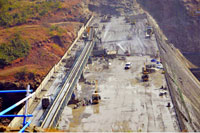
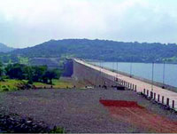
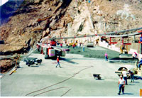
Case Study
|
Ghatghar Dam Project, India
Ghatghar Pumped Storage Scheme a hydropower
generation project of 250 MW capacity, is the first dam in India constructed using
Roller Compacted Concrete (RCC) technology. It is constructed by Irrigation Department
Govt. of Maharashtra. Maharashtra is the third largest state of India, in area as
well as in population. In shape it is four sided with the western side on the Arabian
Sea. The smallest side is the eastern side, which borders Madhya Pradesh, with Gujarat
to the north and Andhra Pradesh, Karnataka and Goa to the south.
It may be recalled that the State Government of Maharashtra had announced in its
2002-03 budget that it proposed an additional 654.25MW of installed capacity for
its hydroelectric projects. This included 250MW for the Ghatghar Pumped Storage
Hydro Electric Project as well as 391.5 MW for the Sardar Sarovar scheme, an inter-State
project that will benefit Gujarat, Rajasthan and Maharashtra.
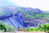
Location
The Ghataghar Dams Project is located on the boundary of the Thane and Ahamadnagar
districts of the Maharashtra State. The Ghataghar Dams consists of three dams -
|

|
Upper Dam, Saddle Dam-1 and Lower Dam, constructed under this scheme with
Roller Compacting Concrete Technology by using dry fly ash with cement. The
lower reservoir and surge well is located in the Sahyadri Range near the village
of Chonde, Shahapur taluka, Thane district. The upper portion of this scheme is
located near village Ghatghar, Akole taluka, Ahmednagar district. Saddle Dam
No. 1, Upper Dam and Lower Dam are built in Roller Compacted Concrete.
A record concreting of over 6, 50,000 m3 in 12 months
was achieved by Patel Engineering Ltd at Ghatghar Roller Compacted Concrete Dam
project.
Dam Details
The upper dam is a gravity dam about 478 m long and 15.50 m high located on Pravara
River near Nashik. It provides storage of 5.87 million cubic metres required
for the operation of the pump storage scheme. The lower dam is also a gravity
dam about 390 m long and 82 m high at the deepest section located on Shai Nalla
at the foot of the continental divide. It provides gross storage of 3.80 million
cubic metres.
Budget
The project was started with an estimated cost of Rs 1,184 crore. On the cost
front the project got a blow - escalating the cost to Rs 1,300 crore. While Rs 400
crore has come in from Japanese Bank of India Co-operation (formerly known as the
Overseas Economic Co-operation of Japan), another Rs 400 crore from the Power Finance
Corporation, and the remaining from the Government of Maharashtra.
Duration
Having started in 1994, the Ghatghar Dams Project was due for completion in
2005, but completed in 2007.
Construction and Contractor
|
The principal contractor for the overall programme is Japan's Nissho Iwai Corp,
with Japanese engineering company, J-Power, providing project management throughout.
J-Power also provided consultancy in 1994 prior to the construction phase, which
started in 1995.The main contractor for the roller compacted concrete dam work is
Patel Engineering Ltd of Jogeshwari, Bombay. The use of fly ash is being regarded
as an innovative approach to the roller compacted concrete method of construction.
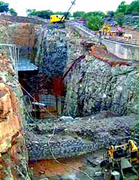
Dirk India Ltd has supplied more than 80,000t of Pozzocrete to the project. It consists
of a downstream vertical shaft of 130m with an 11m diameter, excavated near the
lower reservoir. The Central Mining Research Institute (CMRI) in Nagpur designed
the blasting method for the excavation of the 122m-deep pilot shaft, which was carried
out by contractor R.J. Shah and Co from Bombay. Long hole raise blasting is considered
one of the most economic vertical shaft methods. It is safe and does not involve
cumbersome procedures. It does, however, require a meticulous drilling and blasting
strategy. In the
|
|
Ghatghar vertical shaft, the final 85m was blasted in only
20 days.
Advantages
Advantages of using Roller Compacted Concrete in Dam Construction - The main benefit
of RCC is efficient and speedy construction: the project was completed in
just two years; otherwise about 10 years are required if conventional concrete is
used to construct these dams. The other advantages are higher substitution (up to
70 per cent) of cement by fly ash and reduced heat of hydration, consequently lesser
expenses on cooling infrastructure.
Mechanization of Concrete Laying
Two Schwing Stetter Concrete Batching and Mixing plants – Models HN 3.0 (120
m3/hr) and one HN 4.0 (160 m3/hr) were installed aggregating
to 400 m3/hr batching capacity. The plants had twin shaft mixers and
the control system was Stetter MCI 300 system Principal designers of the project
are EPDC, Japan, in association with Tata Consulting Engineers, India and Malcolm
Dunstan and Associates (MD&A) U.K.
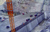
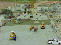
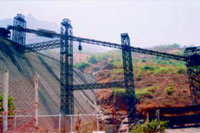
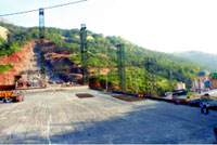
Details of Roller Compacted Concrete Work
Different methods of delivery of RCC into the dam body were studied and finally
best option was selected and the entire site layout was finalized. As per the layout
all the equipment were erected. It was decided to place RCC in two halves so as
to avoid un-planned cold joints.
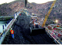
The RCC delivery system comprised of belt conveyor delivering 400 m3
/hr. Four water chilling plants were installed for chilled water supply to three
batching plants and ice plants. Two crushing and screening plants for aggregates
production were installed. One 250 TPH crushing plant and 100 TPH were deployed.
Two 120 TPH and one 150 TPH ice flake plant were commissioned, having automatic
ice handling system. Equipment for RCC placement on dam body comprised of 20-ton
dump trucks for collecting RCC from Belt conveyor and truck unloader, D-5 dozer
for spreading RCC, 10-ton vibratory roller for compaction. It also includes Cranes
for form erection and many other minor equipment like high frequency vibrators,
small roller etc.
The RCC placement was planned to complete in 16 working months excluding one monsoon
of four months. Total 250,000 cum of RCC was placed in the first season. Balance
45,000 cum was to be placed in the next season. Total of more than 6, 50,000 cum
or concrete was placed in 12 working months.
RCC Cooling
|
The temperature of RCC had to be maintained at the placement point between 17-22o
C accordingly the RCC cooling system was designed. Maintaining temperature in this
bracket required pre-chilling of aggregates, use of chilled water and flake ice.
Hence, wet belt conveyor system designed by IIT, Bombay for chilling aggregates
from temperature as high as 43oC was used. This required 1200 TR integrated
water-chilling plant and other sub-systems like water filtration plant, water recirculation
pump, pipeline network and so on.
Major Highlights
Total Concrete Quantity of Roller Compacted Concrete used in 16 Months - 6, 10,903
m3 (Dec 04-Apr 06) (June to Oct 06-no work) resulting in a pouring rate
of Average of 50,908 m3 per month.
Down Pumping
With the same SCHWING BP 25 E at R J Shah & Co. the BP250 was used to pump M25
grade concrete down through 88 mtr. Pipeline which included 04 nos.90 degree bends
and 07 nos. S bends. The Level Difference between pump and point 72 mtrs. (Down),
Top Shot Mobile TSM 30.10 was used extensively for shotcreting of the tunnels.
Concrete Pumping record for the Tunnel Shaft Vertical Pumping was made With a Schwing
BP 250 HDE Concrete Pump, Concrete M/s R.Shah & Co. pumped M25 grade concrete
through a distance of 30 mtr horizontal and 67 mtr vertical.
The Ghatghar Dam Project, the first dam in India constructed using Roller Compacted
Concrete (RCC) technology which was started in the year 1994 was awarded in November
2001 for its technical expertise for the construction of the RCC Dam.
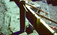
- Conveyor system with self-propelled crawler-placer
- Conveyor system with mobile side discharge belt
- Transverse contraction joint construction with plastic-wrapped
joint form
- Installation of water stop, joint drain, and crack initiator
Conclusion – 26% of the dams build worldwide
have used RCC in the year 1985, which reached 50% in 2005 indicating the popularity
of technology and the pace of development. The application of RCC in India
was nil in 1990 and is 5% in the year 2008. Roller Compacted Concrete Technology
is gaining its popularity year by year gradually but steadily entering the construction
industry.
|
|
Acknowledgement – Authors acknowledge the web- links and websites from which
materials are drawn for this article.
1. Reference - Ghatagar Dams Project, Maharashtra,
India - [http://www.water-technology.net/projects/ghatagar/]
- India's first 84-m high Roller Compacted Concrete dam, Projectmonitor
– The Newspaper [http://www.projectsmonitor.com/detailnews.asp?newsid=7197]
- ACI 207.5R-99, Roller-Compacted Mass Concrete, Reported by ACI
Committee 207
- Gilbert Gedeon, P.E, Roller Compacted Concrete, Course No: S08-001,
Continuing Education and Development, Inc., Stony Point, NY, info@cedengineering.com
Bharathi Ganesh,Associate Professor, Civil Engg. Dept, Global Academy of Technology,
Bangalore
Dr. H. Sharada Bai, Professor, Dept. of Civil Engg. UVCE, Bangalore University,
Bangalore