Structural Behaviour of Glass Panels in Facades
E.Prema latha and Dr. C.Umarani
| The facade is the filter between the climate outside and the conditioned space inside, it determines the appearance of the building and its performance relies on appropriate specification, design, and delivery of a multitude of components and systems. The facade is of paramount importance in terms of building performance and is an important architectural element. It is not only the aesthetics that make the facade so significant - depending on a series of factors such as complexity, materials and finishes, performance and magnitude and location of the project, the facade can account for anything between 15 and 20 per cent of the total construction costs and represent a substantial part of the technical and commercial risk on any given project.
In structural design, glass panels have been traditionally analysed by using methods based on linear elastic theory, where a glass panel is considered as a slab with small deflections compared to its thickness. The linear method gives accurate results as long as the bending stresses govern the behaviour of the panel, which holds true as long as the maximum deflection is less than about half the thickness of the panel. As the deflections increase from that, the change in the geometry of the glass panel begins to influence the behaviour and significant membrane stresses are induced.
In this study non-linear finite element analyses allowing for large deflections were carried out to demonstrate their applicability in the analysis of glass panels. The design methods presented in the codes (such as European design code and ASTM design codes) are more exact and are more complicated than the design methods used before.
For the design of facade systems in India, ASTM / Euro codes are normally followed as Indian codes do not address such information. In the ASTM code of practice the design charts are given for the glass panels with aspect ratios of 1, 2, 3, 4 and 5. Single glass panels normally used in field are having aspect ratios |

|
between one and two. In this study a design chart for the design of glass panels is proposed which can be used by the designers when the designer wants to use 6mm thick glass panels (Normal available glass thickness: 6mm and 10mm) and when the aspect ratios of glass panel are 1, 1.2, 1.4, 1.6, 1.8 and 2.0.
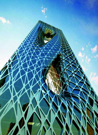
Façades, the first aesthetical feature of a building which distinguishes one building from another, have to fulfil the basic aspects like protection against fire and burglary, climatic influence and environmental pollution. Development in facades has made it more functional, providing designers with the flexibility to create high performance solutions, which are visually exciting, both internally and externally. Glazing system is defined in terms of its functional relationship to the building’s structure. It refers to the cladding, or enclosure of a building as something both separate from and attached to the building’s skeletal framework. Glazing system is a major investment in both the construction and the long-term success of a building. It is not just a barrier to the external envelope of building, it is crucial to the image and the perception of a building. A good glazing design system with excellent performance is essential.
In building industry annealed glass, heat strengthened glass, tempered or toughened glass and laminated glass are used as façade glasses (Ledbetter et al 2006). In the present study, investigation on heat strengthened glass was carried out. Non-linear finite element analyses were carried out to study the behaviour of single glass panels of different aspect ratios. Experimental investigations on glass panels were carried out to validate the results obtained from analytical study. A design chart was prepared which can be used by designers or contractors when the aspect ratio of glass panel varies between 1.0 and 2.0.
Glasses And Their Use In Facades
The following are some of the types of glasses commonly used in building industry as facades (Ledbetter et al 2006), annealed glass, tempered or toughened glass, heat strengthened glass with reflective coating and laminated glass.
Annealed or float glass- Annealed or float glass is glass that has been cooled gradually from a high temperature during manufacture to minimize residual stress. It allows the glass to be cut by scoring and snapping for required size. It is the most commonly available type of flat glass. Standard thicknesses of annealed glass in mm are 3, 4, 6, 8, 10, 12, 15 and 19. This glass is one of the weakest glass types and has a significant potential to break when subjected to over loads. Monolithic annealed glass is not used as a highly stressed structural glass. Annealed glass can be processed to produce other glass types such as tempered, laminated and insulating.
 |
Tempered glass- Tempered glass is an extremely strong glass which is heat treated to a uniform temperature of approximately 6500C and rapidly cooled to induce compressive stresses on the surfaces and edge compression. Tempered or toughened glass gains its added strength from the compressed surfaces. However, if a deep scratch or an impact penetrates the surface, the glass will break into a number of small particles. Toughened glass has been processed in the same way as heat-strengthened glass but has been cooled more rapidly.
The resulting compressive surface stress is higher in magnitude than that in heat-strengthened glass. This gives the glass a bending strength higher than that of heat-strengthened glass. The high strength of the glass means it is far less likely to fail when mechanical or thermal stresses are applied than either annealed or heat strengthened glass. Due to the inherent superior features of tempered glass like more strength, ability to withstand sudden impacts and breaking safely into small pieces, it is used as a safety glazing.
Heat strengthened glass- Heat strengthened glass is valued for its mechanical strength, which is twice that of normal annealed glass though half of fully tempered glass. With the exception of strength and breakage characteristics, heat-strengthened glass retains the normal properties of annealed glass. Heat-strengthened glass provides necessary resistance to thermal stress associated with high performance glazing materials such as tinted glass and reflective glass. It also provides necessary resistance to building heat when used as spandrel glass. Heat strengthened glass provides an interesting compromise between fairly good structural performance and a sufficiently large fragmentation pattern for good post-failure performance.
Laminated glass-Laminated glass is composed of two or more layers of glass with one or more layers of a transparent/ pigmented and specially treated plastic Polyvinyl Butyral (PVB) sandwiched between the glass layers. The glass panes (layers) can be either normal glass or tempered glass. When the glass is broken, fragments tend to adhere to the plastic (PVB) interlayer thereby reducing the risk of injury and helping to resist further damage by weather. The following are some of the types of glasses commonly used in building industry as facades (Ledbetter et al 2006), annealed glass, tempered or toughened glass, heat strengthened glass with reflective coating and laminated glass.
Pure Elasticity
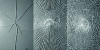
The property of pure elasticity with brittleness means that glass cannot be permanently deformed by load as is the case for most solids such as metals and plastics, and that it fails without warning. Other phenomena affecting the surface flaws and thus the strength of the glass relate to the manufacturing process (with different strengths produced on the tin side and the air side), the duration of the load and presence of water which leads to static fatigue, the physical environment and cleaning processes used. Glass shows an almost perfectly elastic, isotropic behaviour and exhibits brittle fracture. It does not yield plastically, that is why local stress concentrations are not reduced through stress redistribution as it is the case for other construction materials such as steel.
Comparison of the Fracture Pattern
Background
Structural glazing is designed to resist the lateral force induced by wind and sway induced by seismic forces acting on the building. Formerly, very few and often inadequate design guidelines existed for glass structures. Glass companies had developed their own methods for design, but the research background of these methods is confidential information. Therefore, the design of glass structures has been almost mystique for most structural engineers. As the use of more and more demanding glass structures has become common in recent years, there is a need to provide information for designers and contractors about the special properties of glass that govern its structural behaviour.
To evaluate the stress in a glass panel numerically, the classical closed form solution method, the finite difference method and the finite element method can be used. Generally, the classical closed form solution method solving directly the equilibrium equation using the strong formulation can only be used in some very simple cases. The finite difference method involves less computational work than the finite element method but may be limited to standard or simple plate geometry. For glass panels with odd shape and under complicated boundary conditions such as the edges are not completely or fully restrained along their sides, these methods may be too complex, if not impossible. The finite element method is generally considered to be the most versatile in terms of flexibility. In the present study finite element method is used to study the behaviour of glass panel.
In structural design, glass panels have been traditionally analysed by using methods based on linear elastic theory, where a glass panel is considered as a slab with small deflections compared to its thickness. The linear method gives accurate results as long as the bending stresses govern the behaviour of the panel, which holds true as long as the maximum deflection is less than about half the thickness of the panel. As the deflections increase from that, the change in the geometry of the glass panel begins to influence the behaviour and significant membrane stresses are induced.
A plate under the linear assumption for its behaviour does not consider the effect of change of geometry and therefore it resists external loads or pressure by the bending action, in a similar way of a beam with one end pin and the other end roller taking lateral load. However, when the two ends of the beam is restrained against lateral movement and its deflection is significant, a catenary, cable or membrane action is developed. The grossly deformed member will activate an internal component against the external load and this mechanism is much more efficient than the bending action since the former is much stiffer. A large deflection theory for plated structure is therefore generally more efficient when used in design, especially for thin plate where the bending stiffness is small and the membrane can be developed after lateral deflection. The added advantage for using large deflection theory for plates over beams is the natural formation of relatively rigid internal support from material along the four sides of the plate, instead of rigid support provided by external supports or boundary conditions. In this study non-linear finite element analyses allowing for large deflections were carried out to demonstrate their applicability in the analysis of glass panels. (So and Chan).
The ASTM code of practice (ASTM E 1300-02) contains multiple charts and tables. It requires an iterative procedure to converge on an acceptable, efficient design. Twelve charts present the basic strength of AN flat glass for a 60-s duration uniform load. Table 4 of ASTM E 1300-02 provides glass thickness information (one for nominal thickness designations and one for minimum thickness associated with these designations). Tables 1, 2 and 3 of ASTM E 1300-02 provide glass-type factors (for heat-treated glass under different load durations) and Tables 5 and 6 of ASTM E 1300-02 provide load-share factors (for IG and LG under different load durations). The architectural glazing designer enters glass thickness, aspect ratio (length:width), and flexibility factor (ratio of width:thickness for LG) into these tables for a trial design. The designer uses the charts and tables to find the load resistance of this trial design. The designer then uses an iterative (trial-and-error) process to match the load resistance to design load.
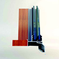
In modern façade, there is a tendency to maximise the transparency of building. One possibility might be to reduce the size of framing member by the use of tension structure (in which the facial glass is fixed to the glass fin by slice plate (Figure 2.1)). Another possibility might be to extend the use of glass to load carrying elements. When glass is used as the load carrying elements, it is usually in the form of glass fin in vertical or slightly sloped direction and glass beam in horizontal direction. Glass fins/beams are generally simply supported. Nowadays, glass fins of span longer than 10 m are commonly used. Even a glass wall specimen with glass fin of span upto 19 m is adopted (Ledbetter et al 2006).
Properties of Heat-strengthened Glass
- Density (approximate) : 2.42 – 2.52 g/cm3
- Tensile strength : 120 to 200 N/sq. mm
- Compressive strength : 1000 N / sq. mm
- Modulus of elasticity : 70 GPa
- Available thickness : 3 mm - 19 mm
- Normally available sizes up to : 2440 mm x 3660mm
- Heat strengthened glass : 2 times stronger than regular glass
- Compression stress of glass : 20…60 N/mm2
- Takes temperature difference up to 100 °C
Experimental Investigation
Testing Methods for Determining the Strength of Glass
| In practice, glazing panels are typically subject to out-of-plane bending when wind pressure is applied. Several test methods have been developed to examine the bending strength of glass. These test methods can be classified as (i) uni-axial bending tests and (ii) biaxial bending tests. With uni-axial bending tests, specimens are supported on two parallel sides and subject to one or two concentrated line loads causing bending in one direction (Figure). The advantage of this test method is that only one principal stress |
 |
is developed at all locations in the glass specimen. Hence, possible influences by other (minor) principal stress have been neglected. The uni-axial bending test with two concentrated line loads is also known as four-point bending test (Figure 2).
With biaxial bending tests, specimens undergo bending in two directions. Biaxial bending tests commonly used in practice are namely ball-on-ring tests, uniform pressure tests (Beason and Morgan 1984) or coaxial double-ring tests.
Details of Glass Panel Specimens
Uniform pressure tests on glass panels were conducted up to failure at the Structural Dynamics Laboratory at Anna University, Chennai. The glass specimens used in all of the tests have the same geometry (1032mm × 860mm × 6mm) and glass type (monolithic, heat strengthened glass plate). To minimize the variation in glass strength, all the specimens were purchased from the same supplier and were transported and stored before testing with methods and in conditions as similar as possible. Aluminium sub-frame section is fixed to form a frame (sub frame) by fixing corners as shown in Figure3. The glass panel of size 1032mm × 860mm × 6mm is fixed with the sub frame using the double sided tape as shown in Figure 4.
A frame was fabricated using aluminium square section of size 50mm x 50mm x 2mm thick for supporting the glass panel while loading with uniform pressure.
Test Set Up
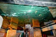
Heat-Strengthened Glass panels of size 1032mm x 860mm x 6mm (aspect ratio 1.2) with simply supported on all four edges were tested under uniform pressure. The loading applied was ramp loading and it was applied using hydraulic jack. Loading arrangements were done in such a way that the load from the jack was applied uniformly over the entire area of the glass plate. The applied load was measured using load cell and the central deflection of the glass panel was measured using LVDT. All the measurements were automatically recorded using data acquisition system (Figure 5). Six samples of glass panels were tested up to failure and the results are reported. Out of the six glass specimens tested, first three specimens (Specimens 1 to 3) were tested up to failure with load duration of ten seconds. A plot of pressure load vs. deflection for the specimens 1,2 and 3 is given Figure 6. All the three specimens show similar pattern of failure at ultimate load as shown.
The other three samples (Specimen 4, 5 and 6) were tested with load duration of 120 seconds, 290 seconds and 380 seconds respectively to study the behaviour of glass panels with varying load rate.
From the experimental results of all the six specimens, it is found that there is less than 5% variation in maximum central deflection of the glass panel against the applied failure load. Comparing the three specimens, the ultimate failure load carrying capacity of glass is increased when the load duration is increased.
Concept of Nonlinear Analysis for Design of Glass Panels
Analysis of glass panel
In recent years, the extensive construction of high rise buildings in many cities in India has further highlighted the importance of conducting more research in the safety of the structures. Glass panels are usually fixed to a building as building envelop. Typically the glass is held in place by means of adhesive strength of silicone sealant and/or mechanical fixing. To evaluate the stress in a glass panel numerically, either the classical closed form solution method, or the finite difference method or the finite element method can be used. Generally, the classical closed form solution method solving directly the equilibrium equation using the strong formulation can only be used in some very simple cases. The finite difference method involves less computational work than the finite element method but may be limited to standard or simple plate geometry.
Linear theory vs. Non-linear theory
 |
 |
A plate under the linear assumption for its behaviour does not consider the effect of change of geometry and therefore it resists external loads or pressure by the bending action, in a similar way of a beam with one end pin and the other end roller taking lateral load. However, when the two ends of the beam is restrained against lateral movement and its deflection is significant, a catenary, cable or membrane action is developed. The grossly deformed member will activate an internal component against the external load and this mechanism is much more efficient than the bending action since the former is much stiffer. A large deflection theory for plated structure is therefore generally more efficient when used in design, especially for thin plate where the bending stiffness is small and the membrane can be developed after lateral deflection. The added advantage for using large deflection theory for plates over beams is the natural formation of relatively rigid internal support from material along the four sides of the plate, instead of rigid support provided by external supports or boundary conditions.
Figure shows an example of glass panel with an overall dimension of 1.032m by 0.860m and having a thickness of 0.006m. The glass panel is simply supported at all the four edges and subjected to a uniform distributed load over its surface. When under wind pressure, the centre diagonal fibre deforms and a component is developed against the external wind. To maintain equilibrium, the fibre along the four sides will be in compression to provide ‘supports’ to the tension diagonal fibre. The larger the deflection, the more effective action will be developed in the system.
This glass panel with an overall dimension of 1032mmx860mm and having a thickness of 6mm is analysed using both linear theory and nonlinear theory. The glass panel is simply supported at all the four edges and subjected to a uniformly distributed load over its surface. The results from both analyses are presented in Figures 7.
Non-linear analysis for glass panel
The advantage of the present method is its versatility in handling complex loading and boundary conditions. The longer computational time has been effectively offset by the adoption of the efficient incremental-iterative minimum residual displacement method of analysis and the availability of fast personal computers. A large deflection theory for plated structure is therefore generally more efficient when used in design, especially for thin plate where the bending stiffness is small and the membrane can be developed after lateral deflection. The added advantage for using large deflection theory for plates over beams is the natural formation of relatively rigid internal support from material along the four sides of the plate, instead of rigid support provided by external supports or boundary conditions. In this study non-linear finite element analyses allowing for large deflections were carried out to demonstrate their applicability in the analysis of glass panels (So and Chan 2006).
The large deflection behaviour of thin glass plate is demonstrated. Surface stress is plotted for the ease of understanding of nonlinear behaviour when the glass undergoes large deformation. Glass panel is commonly used in curtain walls and glass structures. Owing to possible saving in material weight, nonlinear and large deflection plate theory has to be used.
Description and validation of Analytical model
There are several theoretical methods, the earliest developed in 1930's, to analyse glass panels by taking into account the non-linearity induced by large deflections, but the finite element method (FEM) is generally considered to be the most versatile. The deflection in laterally loaded glass panels is non-linear. Consequently, conventional analytical techniques for plates are inadequate. Numerical analytical techniques with the assistance of high speed computers required to solve the 4th order differential equation for thin plate behaviour have made the task of the non-linear analysis now feasible. The use of finite element techniques has enhanced our appreciation for the interaction of the various parameters that influence thin glass panel behaviour. By using FEM, solutions for complicated geometry, loading and boundary conditions can be obtained quite comfortable.
Moreover, the method is familiar to most engineers. A former disadvantage of heavy computational time has been remarkably reduced by the powerful incremental-iterative non-linear numerical methods developed and the low price and fastness of today's microcomputers.
Software ABAQUS is used to model analyse the glass plate. Elements of type solid continuum elements C3D8I (ABAQUS) are chosen, since they are known to give accurate results for the geometrically non-linear large-deformation analysis. The element type C3D8I is first-order full integration incompatible mode elements with eight nodes. Each element in ABAQUS has a unique name, such as C3D8I. The element name identifies each of the five aspects of an element. Five aspects of an element characterize its behaviour: Family, Degrees of freedom (directly related to the element family), Formulation, Number of nodes, Integration.
To perform the analytical analysis, it is necessary to input the material properties such as, modulus of elasticity E and Poisson’s ratio n for the perfectly elastic material model of glass. For this study, the following material properties of soda-lime silicate float glass in accordance with the literature review were considered (Ledbetter et al 2006). Various values for material properties of float glass are found in literature. The modulus of elasticity (E) varies between 70000MPa and 75000MPa and Poisson’s ratio (n) between 0.20 and 0.25.
The influence of altering Poisson's ratio between the limit values given in the standard was examined. The comparison was made for the values n= 0.22, n = 0.23 and n = 0.25 in the analysis of glass panel 1032mm x 860mm x 6mm loaded by a uniformly distributed pressure load increasing from q = 0 kPa to q = 12.0 kPa and Pressure load vs. deflection graph for varying Poisson’s ratio is shown in Figure 8.
Validation of Analytical Work with Literature Paper
The validity of the analytical model was ensured by comparison of results with the work done by Vallabhan 1983, whose results have been referred in ASTM code E 1300-02 “Standard Practice for Determining Load Resistance of Glass in Buildings”. A rectangular glass panel with all four edges simply supported having dimensions of a = 60” (1524 mm), b = 96” (2438 mm), t = 0.225” (5.72 mm) with E = 10 x 106 psi (68.9 GPa) and ?? = 0.22 subjected to uniform pressure was analysed by Vallabhan 1983 (a paper published in ASCE and this paper has been referred in ASTM code E 1300-02 “Standard Practice for Determining Load Resistance of Glass in Buildings”).
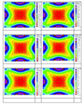
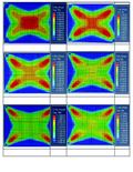
Vallabhan has used finite difference method for solving the problem. To validate the finite element model of glass panel, the problem solved by Vallabhan using finite difference method was analysed using nonlinear finite element analysis. The deflection/displacement results obtained from analytical investigation and from literature, for varying lateral pressures are tabulated in Table 6.4. Comparison of analytical investigation and literature graph (pressure load vs. deflection) is presented in Figure. The results of both analyses compare well. The displacement contours are shown in Figure. The maximum principal stress contours are plotted and are presented in Figure (Vallabhan 1983). This demonstrates the non-linearity of glass plate and the migration of maximum stresses from the centre towards the support.
Analytical investigation on glass panel
For analytical investigation, single rectangular glass panels with aspect ratios varying from 1 to 2 are considered. For each aspect ratio, three different sizes of glass panels are considered. Analytical modelling results for aspect ratios of 1, 1.2, 1.4, 1.6, 1.8 and 2.0 of glass panel was carried out using non-linear finite element analysis ABAQUS software. The pressure load vs. deflection charts for the aspect ratios AS1.0, AS1.2, AS 1.4, AS 1.6, AS 1.8, and AS 2.0 (three different sizes for each aspect ratio) of glass panels are presented.
Based on the type of glass used, glass type factor is to be chosen from Table 1 of ASTM (E-1300-02) is presented in Figure below. The non factored load is to be multiplied with GTF for evaluating the load. Then load x area2 value is to be calculated. Referring to Figure A1.6 (lower chart) of ASTM, the calculated value of load x area2 and the aspect ratio of the glass panel, corresponding central deflection can be found.
The main drawback of ASTM lower chart is that the plots are given for aspect ratios 1, 2, 3, 4 and 5 for 6 mm thick glass with four sides simply supported. If the aspect ratio of the glass panel is 1 or 2, it is easy to find out the corresponding deflection from ASTM. For Indian conditions the aspect ratio of single 6 mm thick glass normally used in field lies between the 1 and 2. Interpolation of lateral deflection from ASTM chart misleads to design of glass panels.
Hence detailed design chart is developed as shown in Figure below which can be used to determine the maximum central deflection of 6 mm single glass panel with four edges simply supported, for aspect ratios between 1 and 2. Separate curves are presented for the aspect ratios of AS 1.0, AS 1.2, AS 1.4, AS1.6, AS1.8 and AS 2.0. This design chart can be used by the designers for the design of glass panels of 6 mm thickness.
Conclusions
With the trend of globalization, it appears that Indian engineers need to equip themselves on various new techniques for enhancing their competitiveness and non-linear analysis and design is considered to be one of these advanced techniques. Glass panel is commonly used in curtain walls and glass structures. Owing to possible saving in material weight, nonlinear and large deflection plate theory has to be used. When the ABAQUS Standard software is used for the analysis of glass panel, the element of type solid continuum element C3D8I can be used which can represent the behaviour of glass panel very well.
A design chart was prepared which can be used by designers or contractors when the aspect ratio of glass panel varies between 1.0 and 2.0.
References
1. AAMA (American Architectural Manufacturers Association), “Curtain Wall Deisgn Guide Manual”, 1996.
2. Aki Vuolio, “Structural behaviour of glass structures in Facades” Espoo a thesis submitted for Doctor of Philosophy, 2003.
3. Andrew So, Benny Lai and Chan, S.L. “Concept of Nonlinear Analysis and Design of Glass Panels”, 2006,
4. AS1288, Glass in building-Selection and installation. Sydney: Standard Australia, 2006.
5. ASTM E 1300-02 Standard practice for determining load resistance of glass in buildings.
6. Calderone and Melbourne, W.H. “The behaviour of glass under wind loading”, Department of Mechanical Engineering, Monash University, Wellington Road, Clayton, Vic. 3168, Australia, 1993.
7. Girija Vallabhan C.V. and Gee David Chou “Interactive Nonlinear Analysis of Insulating Glass Units”, ASCE, Journal of Structural Engineering, Vol. 112, No. 20674, 1986.
8. Girija Vallabhan, C.V. “Iterative Analysis of Nonlinear Glass Plates”, ASCE, Journal of Structural Engineering, Vol. 109, No. 17739, 1983.
9. Iizumi, E. and Kopp, G.A. “Behaviour of glass plates under pressure loading”, 1st American Association for Wind Engineering (AAWE) – Workshop, AAWE, Colorado, USA, 2008.
10. Ilham Nurhuda, “Ultimate Behaviour of Annealed Glass Panels Subject to Out-of-plane Static and Transient Action”. A thesis submitted for Doctor of Philosophy January 2011.
11. Lynn Beason, W. and James Morgan, R. “Glass Failure Prediction Model”, ASCE, Journal of Structural Engineering, Vol. 110, No. 2, 1984.
Mrs.E.Prema Latha M.S (by Research) holds a B.E (Civil) from Government College of Technology, Coimbatore, MS(by Research) from College of Engineering, Guindy, Anna University, Chennai. Her area of research is “Structural behaviour of Glass Panels in Facades”.
Worked as Design head for 3 yrs in Noble Consolidated Glazing’s Ltd, Chennai, before doing her Research in this area. Curently, she is working as Assistant Professor (Sr.G), Dept of Civil Engineering, SRM University, Ramapuram Campus, Chennai. Her areas of interest include construction engineering, Strength of materials, Design of Tall buildings, Wind Engineering and Project coordination.
E. Prema Latha