Tbilisi Public Service Hall, Tbilisi, Georgia
A Flower Symbol
A structure can take a form of graceful contour, if planned and executed well. A recent project which excels in both architecture and form is the Tbilisi Public Service Hall situated in the central area of the city of Georgia. The project received a grand opening in 2012. This much awaited project was designed by Italian based architect firm Fuksas. The studio is led by Massimiliano Fuksas and Doriana O. Mandrelli. The Studio is a leading international architect firm with a track record delivering acclaimed project and plays an important role in the international architectural context since 1980's.
Size of the Project
| Tbilisi Public Service Hall is located at 2, Sanapiro St. Tbilisi, Georgia. The gross building area preview is about 42000,00 square meters. The triangular parcel is 408.90 meters long on the North-Eastern edge, by the Kura River, and 138 meters long on the North-Western side. The parcel follows Sanapiro Street for 345.48 meters on the South-Western border. The site is relatively flat and the level differences do not exceed 1.41 meters or a 1% slope. The project is located inside a new developed green area |
 |
called Rhike Park, in Tbilisi, Georgia. The building is made up of 7 volumes that contain offices (each volume is made up of 4 floors located on different levels). These volumes are placed around a "central public square", which is the core of the project and is spaced for front office service. Offices are connected to each other by internal footbridges that stretch on different levels.
Project Description
The new project comes out from the Client desire to include a single architectural element the headquarters of the National and the Civil registry of the Central Bank of Georgia.
Describing the concept of the project, Ar. Fuksas says, "The concept of the project comes from the flower symbol. A recognizable symbol related to rebirth. For the spectacular coverage of 11 petals, we thought a structure likes tree. The petals, or leaves, are inspired by nature, landscape. The project was conceived as a piece of panorama, a forest, where the roof is supported by long and strong steel trees."
He further adds, "The "boxed" boundary, decided in the last proposal to improve the natural lighting and aeration of the offices and to optimize the walkway distribution was upgraded to fully optimize the use of space. On the exterior side of the building are allocated spaces for natural light, on the other side, the meeting rooms, the server room and the archives overlook the inner monolithic square. The "House of Justice" consists of two parts contained into a unique building that correspond to the Registry Agencies and the National Bank of Georgia."
On the Ground Floor, several public agency counters and associated areas were divided into two parts of the building. Inside the square, the allocated areas are distributed together with part of the Front Office program. In correspondence with the Agencies, the ground floor includes the Front and part of the Back Offices. Behind the main entrance are located a cafeteria while the IT shops is below the bank; a second cafeteria is located on the opposite side of the hall. On the top of the hall, big holes let the light enter inside the main plaza.
The First Floor is allocated to the remaining Back Office of both the Agencies. Several lift-cage documents connect the upper level to the Ground Floor Back Office.
The Second Floor receives the whole National Registry Agency offices, several meeting rooms and the access to the Press Conference Hall. The access is regulated by a check point in the Ground floor.
Third Floor is dedicated to the Civil Registry Agency. The Fourth Floor is located to the offices of Ministry of Energy and several meeting rooms.
On the other side of the square are the Agency offices, located in the Headquarters of the National Bank of Georgia. These offices integrate every exigencies of headquarter of a national bank who follow the same concept to the rest of the building and are organized advantaging the natural lighting of the offices.
Ground Floor is located to the Entrance Hall with the associated offices. The entrance is directly connected with the private parking and allows an easy and covered access to the waiting car in front of the door. Ground Floor also house some facilities and retail spaces.
President office and the rest of Head offices are located on the Fifth Floor.
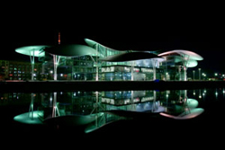
Concept Design
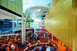
| The present project improved the shape to refine the office theme to the contest without losing the primary concept for the House of Democracy: transparency. The same desire to materialize the institutions symbiotic energy via an open structure which is lit from a variety of points, continue being the first point of the concept. The light is freely reflected throughout the structure in order to create multiple reflections, mirroring the users’ movement throughout the space. The curved shape will be proudly viewed by the citizens in daylight as well as during the night, thanking the artificial lights systems who enhanced the building. The structure contains the National Bank of Georgia Headquarter, the National and Civil Registry as well as Offices for the Ministry of Energy and all the Public Institutions counters to provide efficient services to the citizens. The space is also distributed to non institutional services, such as insurances, real estate agencies, banks. Users have to access information through well established points which are scattered within the open space. |
 |
For this reason, the distributed program grows mainly around a great central hall, a covered space in which citizens and services are connected. Other services like hearing halls, stores, cafes and waiting rooms overlook the space and are mixed between them to allow the public to be informed in different information boxes.
Explaining about the unique design Ar. Doriana says, "The design concept wants to poetically express the changes and the renovations that are acting at the moment in Tbilisi. This effort was achieved using innovative shapes to house classic programs like office and citizens service spaces. These spaces create an interesting relationship between user, function and architecture."
The building is covered by a series of great leaves elliptical shaped surfaces, whose axis rotates and grows in the longitudinal direction. Similar in shape, the elements differ in function and in relationship with the surrounding elements. Some petals are perforated to create large skylights and permit to natural light to illuminate the great hall.
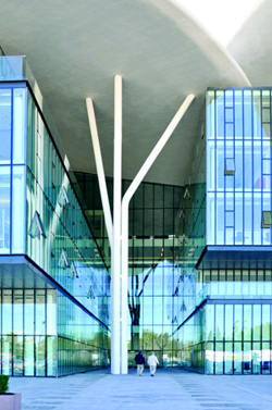
The Petals, Steel Pillars & Glass Facade
Volumes and the central public space are towered above by 11 big "petals" that are independent both formally and structurally from the rest of the building. Three of those big petals cover the central space. The petals, different for their geometry and dimension, reaches almost 35 meters and they are supported by a structure of steel pillars with a tree shape, visible, as well as the petals, externally and internally from the building.
Elucidating about the challenges encountered at the design level Ar. Fuksas says, "The most interesting challenge in the design phase was to combine the idea of the project with the functions of the building. The design of the petals and of the tree structure has been combined with the interior of the building. The volumes of the offices have a regular plan and are on different levels. Walkways are linked to different volumes, while activities for the public are concentrated on the first floor in the main 'square'. The project has managed to combine a sculptural design with the functions provided by the program."
The main steel pillars, with a tree shape, are formed by three tubular profile cables of section 508x35mm connected together by stiffening profiles of circular full section of 150mm diameter. These profiles allow the three main elements to work together and stabilize them.
Each main tubular element, 508x35mm, goes to give a point of support to the petals of coverage. The support is formed by 4 arms always in tubular profiles, with variable section and thickness that are connected with the elements of the upper part of the reticular of the petal.
All the main pillars are connected using these four arms to the petals they encounter, whether the pillar stops at the petal or it goes through it to support even the upper petal.
Further support to the petals is given by the steel pillars which in some cases continue from the coverage of the buildings The connection of the petals between the pillars and reticular coverage has been studied to ensure only the support for vertical loads, avoiding transmitting the horizontal actions of the petals cover the pillars, which would lead them to failure. Thus, the multi-directional spherical support studied allows to release horizontal forces that the steel pillars continue from the buildings coverage.
Structure of the petals coverage
The petals of coverage have a spatial network structure made of tubular profiles completely welded together, of variable thickness and section following a choice of weight optimization of the structure itself. The reticular are in two main directions of each petal, vertical and horizontal if viewed in plan, and each reticular is characterized by a higher current, one lower and diagonal stiffening profiles.
The shape of each reticular and the high are different from each other to follow in a precise manner the architectural shape of the petals.
The space of the lattice is variable, mesh 2x2m or mesh 1x1m, depending on the area of the individual petals and snow and wind loads. The space is always 1x1m in correspondence of the support of the main pillars and secondary steel pillars where the connection to the roof structure is realized with 4 tubular elements
Petals facade connection
Among the petals that are at different levels are the glass facades. The main characteristic of these facades is that these have been released completely from the structure of the petals, allowing relative movements between the facade and the spatial network structure of coverage. This decision was taken to prevent that any movement of the cover, mainly due to oscillations for snow loads, wind or thermal expansion, can lead to the crisis of the glass.
Description of Structural System
The complex structure "House of Justice" consists of 9 buildings, arranged to form a quadrilateral of size plant of about 140x95 m, inside a covered square size of 52x52 m. The nine buildings have been designated by the letters A to H, which shows the layout of that classification.
These buildings, which have a number of different decks to each other, have a common curve roof, which develops a plan surface about 15000 square meters. They are also linked in above-ground floor, through pedestrian walkways.
These buildings also have a common underground floor, at an altitude of -4.10 m from ground level, where spaces will be dedicated largely to local technical plant.
The types of structures in this work can be summarized as follows.
The foundation structures are concrete plates thick 40 cm at Underground floor, 25 cm at Ground Floor and 30 cm in the area of Central Square. These plates are supported on piles to depth of 10 m and diameters variables from 52/62 cm to 80/90 cm to 108/118 cm, with connecting foundation reinforced concrete beams of section BxH =50x60 cm or BxH=200x30 in the area of central square. To size these foundation structures, reference is made to the geological report called "Factual Technical Report on Preliminary Geotechnical Survey of Justice House" carried out by Geo Engineering Ltd.
The underground floor’s locals will be contained by reinforced concrete walls 30 cm thick with reinforced concrete pillars of enough section to hold the base plates of steel columns that stand out from the ground floor.
The floors on the ground floor in the underground floor shape will be in full reinforced concrete slab thickness of 25 cm, with intrados concrete beams, and the floor of the central technical area are predalle lightened composed of concrete ribs and polystirene blocks, high equal to 4+31+5=40 cm.
The building structures that stand out from the ground floor are frame type with steel principal alveolar beams and tubular columns.
The building D has two bracing concrete walls thick 30 cm. Various buildings have a number of different levels, from a minimum of 4 decks to a maximum of 6 decks (Building C).
The floor plans are corrugated hi-bond sheet 11 cm thick, placed in light on alveolar beams. These principal steel beams, with the presence of holes in the profiles, will allow the passage of pipes plant.
The roof is composed of multiple "petals", whose structure is composed of steel truss of variable height and light, placed at a distance of 2 m, with doubling at 1 m at the main pillar, or portions of the petal more stressed or deformed.
Roof Structure Global View
These cover shells are supported by steel pillars arranged in tripod, which sometimes also intercepted two petals of coverage. Locally some pillars of the buildings will continue to cover shells, with function of local support. These pillars will be equipped at the top with spherical multidirectional hinges, to realize seismic joint between underlying buildings and roof’s petals.
The main pillars are connected at reinforced concrete footings to 9 piles of 80 cm diameter and 10 m depth, through a single base plate.
The head is connected to the timber-framed trusses through stumps four-way to the upper longitudinal currents.
Structural Schematization and Calculation Standard of the Stresses
The program schematizes the structure introducing in the following order: foundations, also on different levels, slabs, ribbed slabs, plinths and foundation beams all based on elastic Winkler ground, vertical elements, pillars and r.c. walls also with holes, bases formed of horizontal and inclined floors (pitches), and relative plane beams and of pitch; it is allowed also the introduction of storey height r.c. prismatic elements with possibility of connection in inclined with floors set at different levels. The structural nodes can be connected only to beams, pillars and walls, simulating in this way infinitely deformable scaffolds in the plane, or to slab elements with thickness declared by the user simulating in this way finite stiffness scaffolds.
| The nodes belonging to the horizontal scaffolds can be rigidly connected to one or more main nodes lying in the scaffold plane; generally one main node coincides with the mass centre of the masses. Such option, besides reducing significantly the times of elaboration, eliminates the numeric approximations connected to the use of slab elements when it is requested an analysis with infinitely stiff scaffolds. As regards the loads, during the data input, are defined, a number chosen by the user, of elementary |
 |
load conditions that, in addition to the seismic actions and thermal variations, are combined through multiplicative coefficients to supply the combinations requested for the successive checks. The off-centering effect of the horizontal forces, induced for example by plane twisting for constructions in seismic area, is simulated introducing additional plane eccentricities which constitute further load elementary conditions to accumulate and combine according the previous paragraph standards.
Typologically, the beams and the walls are allowed with loads evenly distributed and trapezoidal loads; along the rods and in the crossing nodes of the ties it is also possible to define forces components and concentrated couples anyhow are directed in the space. Temperature distributions are provided, with intensity chosen by the user, agent also on single portions of structure.
| The stresses calculation is based on the following assumptions and modalities: - beams and pillars deformable with normal stress, deflected bending, deflected shear and twisted moment. Reductive coefficients are provided of the inertia moments chosen by the user to consider the reduction of the bending and twisting stiffness for effect of the concrete conglomerate cracks. It is provided a multiplier of the pillars axial stiffness to consider, even though approximatively, the shortening of pillars for normal stress during the construction. - the foundation beams on Winkler ground are solved in closed way through a specific finite element; - the r.c. walls are analyzed schematizing them as plate-slab elements discretized with maximum pitch assigned during the data input; - the masonry walls can be schematized using slab-plate elements with reduced bending thickness as regards the membranal thickness.-The plinths on Winkler ground are modelled |
 |
introducing elastoplastic vertical springs. The horizontal translation chosen by the user is blocked or managed by horizontal springs of reaction module proportional to the vertical one. The piles are modelled subdividing the rod into more rods immersed into soils with stratigraphy defined by the user. In the nodes of division between the rods are introduced axial-symmetric elasto-plastic springs preloaded with the rest push that have as minimum limit precision the active push and as maximum limit precision the passive push modifiable through proper coefficients. - the plinths on piles are modelled through highly stiff rods connecting one point of the structure in elevation with the rods simulating the presence of piles;- the plates are discretized in a finite number of slab-plate elements with maximum pitch assigned during the data input; in the case of foundation slabs the nodes are connected to the ground by means of springs with stiffnesses in the vertical and on request also horizontal translation.-
The deformability in the plane of the planes declared not infinitely rigid and of the pitches (inclined planed) can be controlled through the input of membranal elements in the floor areas. - The off-centerings among rod elements are automatically managed by the program through the introduction of rigid local connections.- At the ends of rod elements it is possible to introduce traditional releases as partial hinges (that convey a part of what they would convey in rigid connection conditions) or plastic hinges.-
At the ends of bi-dimensional elements it is possible to introduce releases with partial hinges of the bending moment having as axis the element border.- The calculation of the seism effects is performed, according the choice of the user, with linear static analysis, with modal dynamic analysis or with non linear static analysis, according to the rules adopted. The masses, in the case of scaffolds declared stiff, are concentrated in the main nodes of plane, otherwise they are considered diffused in the nodes lying on the same scaffold. In the case of seismic analysis is also checked the storey height displacements.
Conclusion
In the present context, most of the public buildings are no more a regular tall buildings. These buildings have been portrayed entirely in a different form where architect plays an important role. Expressing his views on the same Ar. Fuksas concludes, "The towers naturally fit into the urban context, as well as any other building, if they want to belong to a place and its inhabitants. The towers become necessary when the density collides with a measured use of space."
Fact File
Project: Tbilisi Public Service Hall
Site: Tbilisi, Georgia
Address: Sanapiro Street 2
Period: 2010-2012
Client: LEPL Civil Registry Agency - Giorgi Vashadze / LEPL National Public Registry Agency
Architectural Project: Massimiliano and Doriana Fuksas
Project Leader: Emiliano Scotti
Project Team: Riccardo Ferrari, Matteo Malatesta
Model Makers: Nicola Cabiati
Surface: Superficie totale costruita: 42.000 m²
Volume total construction: 265.000 cubic meter
Main hall surface: 4 385 m²
Leaves” surface: 24 800 m²
Structural glass (enclosure): 2 390 m
Facade: 11 800 m²
Parking Plots: 838 (426 coperti)
Engineering: Studio Sarti, AI Engineering
General Contractor: Huachuan Georgia Company LTD
Program: National Bank of Georgia
LEPL Civil Registry Agency
LEPL National Public Registry Agency
Ministry of Energy
Civil and National Registry Agency: 280 public desk
Press Room: 290 MQ (150 seats) + Foyer 100 m²
Retails and Facilities: 400 m²
Terraces: 1860 m²
Material Structure: Reinforced concrete and steel
“Leaves” structure: tridimensional steel reticular
"Leaves" coating: glass fiber and epodossic resine
Facades: structural glass and cellular glass
Acknowledgement
The additional technical inputs have been received from Studio Sarti, Structural Consultant - Rimini, Italy.