Trenchless Technology (TT)
Introduction
Trenchless Technology is a branch of construction engineering dealing with techniques and related equipment used to develop, maintain and renew subsurface utility networks without excavating continuous trenches. It is a branch of applied engineering, which is State-of-Art, used to develop, manage, and renew continuous cabled and piped networks for transferring signals and fluids respectively. Major applications of these techniques are for Water Supply, Rainwater Disposal, Sewer Disposal, Gas, and Petrochemical products, electrical and telecom signals and other underground networks.1
Thunder Driller
The term ‘Trenchless Technology’ is commonly used to describe a wide spectrum of technologies, processes, and techniques for creating holes without disturbing the surface. Trenchless technology is the technology for placing new pipe, cable, or conduit in the ground between two defined points without continuous, open-cut excavation between them. With the advancement of equipment technology, it is now possible to produce holes ranging in size from as small as a few inches to 6 feet (2 meters) or larger depending on the need and the application.
Mechanical Drill Head
The purpose of trenchless construction is to eliminate disturbing surface installations or improvements. For example, open-cutting across a road disrupts traffic, may damage the roadbed or surface, and requires a costly restoration of the open-cut section to its original condition.
Cased Augur Boring
TT-Advantages
- Enhanced worker and public safety.
- Reduced risk of damage to nearby nature, structures and utilities.
- Reduced disruption to surrounding businesses, residents and the environment.
- Price advantage over traditional open-cut options of underground installations.
- Eco friendly with low disruption, minimum excavation and often - reduced cost capabilities.
- Rehabilitation time for affected areas can be much shorter than open-cut operations.
- Possibility of trenchless operations even beneath existing services like buildings etc.
- Minimised disturbances to routine city life.
- Pipelines can be installed to gradients of 0.5% to 70% with accuracy.
Bore Creation
Appropriate and systematic Bore creation methods for boring have to be adopted to fulfil the required functionality. Proper understanding of the soil condition prior to the implementation is also of prime importance. Following several methods are used for forming the bore of a desired diameter and a few important ones are discussed here.
- Thrust boring
- Impact boring
- Augur Boring
- Rotary drilling
- Micro-tunnelling
- Water-jet cutting
- Wet boring
- Pipe jacking
All the above eight techniques follow one of the three principles namely;
- First Principle-The first technique compresses the material into the surrounding earth without producing cuttings or spoil. This method works in a limited number of soils (usually porous, moist, and compactable) and at shallower depths (typically 1.8 meters or less). Compaction techniques usually require high-thrust loads and may result in damage to nearby structures or facilities because the soil is being displaced.
- Second Principle-The second method, to crush the earth by using impact or percussion hammers, is usually applied only to very hard rock.
- Third Principle-The third method is to cut (i.e., scrape, machine, grind, crush, or erode) the material with a drill bit to produce cuttings, which are then removed by either a circulating fluid or a mechanical conveyor.
Application of a particular method depends on the material to be bored, the size and length of the bore, the need to be directionally controlled, and other environmental parameters. There is a wide variety of equipment configurations for small diameter boring, including some combinations or hybrids of basic methods. These three methods are further divided into the eight different techniques or methodologies. Some of the commonly used trenchless technologies are discussed here.
Thrust Boring
Thrust Boring Process
Traditionally Thrust Boring has been seen as a methodology used for bores up to approximately 60–70 m in length, with limited accuracy due to being non-steered. In thrust boring, a borehole is formed by applying axial thrust to solid or closed-end push rods. This action causes local compression and displacement of soil into the surrounding soil at the front of the system. Primary characteristics of the method are that it produces no spoil and the push rods are not rotated or impacted.
A typical thrust-boring system consists of a small jacking frame, one or more hydraulic rams, a rod-gripping device, and push rods. A tapered boring head, slightly larger in diameter than the rods, is normally attached to the lead rod to facilitate penetration and provide diametrical clearance between the rods and the borehole. Power to the push/pull cylinder (or ram) is typically provided by a portable hydraulic power supply.
Operation of the system is relatively simple. A small pit is dug slightly deeper than the specified burial depth of the underground line. The jacking frame is then lowered into the pit, aligned, and anchored to absorb the applied loads. As most thrust-boring equipment operates in both push and pull modes, the anchoring is done either by placing a T-bar in a slot cut perpendicular to the main pit or by jacking reaction plates against the back and front walls of the pit.
One by one, sections of pipe, normally 3 to 5 feet (l to 1.7 meters) in length, are placed into the frame, coupled, and pushed forward into the soil by the ramrod gripper assembly. The rod-gripping assembly, which transmits the load to the push rods, can be a locking cam, steel jaws, or an end connector, depending on the manufacturer. Drive speeds range from 1 to 4 feet (0.3 to 1.3 meters) per minute, depending on soil conditions, and usually decrease as the drive span increases in length.
Thrust-boring equipment is most effective when used in highly compressible soils such as loams and silts. In general, because of the high loads that will be required to compress the soil and overcome drag on the rods, its use should be avoided in very stiff soils. Sufficient ground cover (2 to 4 feet or .6 to 1.2 meters) must be maintained above the push rods to prevent heave of the surface and/or rising of the rods to the surface.
Impact Boring
Impact Moling
Impact Moling Equipment forms a horizontal hole by compacting and displacing the soil to form an opening. These tools have a cylindrical or torpedo shape and are energized by air or hydraulic power. The compressed air or hydraulic fluid drives a piston within the piercing tool against a cutting head or anvil at the front of the tool. Piercing tools are also known as moles, gophers, and missiles. The names relate to their burrowing action or shape. These tools are basically of simple design and easy to operate. Besides the tool itself, only a mobile compressor and hose are necessary for operation. The simplicity and relative low cost are the major attractions of this equipment.
Piercing tools have a tendency to drift toward the softer soils, and the operator may not know when this tendency occurs. Therefore, the tools can sometimes bury themselves; surface in the middle of roads; or in the worst case, damage nearby utility lines. In the last ten years, manufacturers have made significant improvements in the stability and reliability of these tools. Also, many manufacturers have added a reversing feature, which permits the operator to back out the tool if it becomes stuck against an object or deviates from its desired path.
Piercing tools are available in a wide range of diameters, varying from 1.75 to 10 inches (40 to 250 mm). The most common size is 4 inches (l00 mm) although the 2-inch (50 mm) model has become popular in the last few years, particularly for the installation of services. After an initial pilot hole is created, it is possible to back ream and create a large size. Often, this is the preferred method for creating larger holes. The typical operating distance for piercing tools is less than 60 feet (20 meters), although bores of over 200 feet (60 meters) have been reported by some users. Penetration rates for piercing tools are 30 to 60 feet/hour (9 to 18 m/hr). These rates depend on soil type and will be significantly affected by rocks and hard or soft soils. Piercing tools work best in clays and other unconsolidated materials.
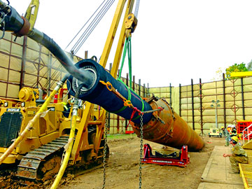
Impact Ramming
Impact ramming is a relatively new concept based on the principles and equipment used in piercing tools. In impact ramming, a piercing tool operates as an impact device to drive a pipe or other conduit into the ground. The pipe installed by ramming equipment is typically used as a casing for other pipes or cables to be installed at a later time.
The piercing tool drives the pipe the length of the entry pipe and then is returned to its original position as each new section of pipe is added. The next section of pipe is inserted into the launch pit and welded to the first section. The length of the launch pit is determined by the length of the pipe selected. Ramming machines operate at a slower stroke than impact moles, typically 30 to 50 percent fewer blows per minute. Chains or other methods of attachments are sometimes used to prevent the impact device and pipe from dislodging.
 |
Most often, open-end pipe is driven through the soil. The soil enters the open pipe and is removed after the boring operation is completed. Soil in the pipe is pushed out with compressed air or washed out with water jets. Occasionally, closed-end pipe is driven with an impact ramming device. In this case, the soil will be displaced and compacted. This technique tends to limit the diameter of the pipe and the length of the bore more than the open-end approach.
Impact ramming can be used in a variety of soil environments including clays, silts, sands, cobbles, and gravels. This technique may successfully operate in environments not suitable for piercing tools. The operator needs to make trade-offs between the length of the pipe and the length of the launch pit. The launch pit ranges from 25 feet (8 meters) for small-diameter pipes up to 36 feet (II meters) for larger pipes and equipment. Impact ramming with open-end pipes minimizes disturbance to the soil from heaving (such as is created with piercing tools). However, a blockage could be created at the end of the rammed pipe and cause significant disturbance. Impact ramming may not be desirable in some areas because of the loud noise created by the ramming technique.
Auger Boring
Auger boring is a horizontal rotary earth-boring process. It was originally developed in the 1950s for the US. Oil and gas industry when cross-country pipelines had to go under railways and multilane roads and highways. This type of work continues to be its major application, although there are many other uses. The basic equipment consists of several elements, namely, a cutter head at the leading end of a string of flight augers, which are connected in turn to a power unit in the drive pit. The auger flights rotated by the power unit provide the driving force to the head and remove the cuttings from the bore.
Auger-bore rigs vary greatly from manufacturer to manufacturer but basically consist of a power unit that is connected through a drive chuck to the flight auger. A crane is necessary for handling the equipment and casings. They also incorporate a pipe-jacking rig in the sub frame, which allows the casings to be moved forward as the bore advances. The thrust is transmitted onto the casing through a thrust ring.
Augur boring is classified into two categories namely; Free Boring and Case Boring.
Free Boring- When a horizontal hole is bored without any casing, it is sometimes referred to as free boring. In a number of countries, uncased boring under public property, such as roads, is not permitted. Although any standard machine can bore without a casing, some small machines do not provide any simultaneous casing capability. They are used for forming a small-diameter hole, usually under private property, for service connections in the range of2 to 6 inches (50 to 150 mm). Machines for this type of work have small power packs and short-base frames so that they are easily transportable and work from small pits of around 5.5 feet (1.7 meters) or less in length.
Case Boring-In case of larger diameter boring, casing becomes necessary to avoid risk of internal collapse of soil structure. The majority of auger-bore work involves the simultaneous casing of the hole. Often, as in railway crossings, this is an inherent part of the specification. The casings used are steel tubes, which are most often joined together by welding.
Cutting Heads- Choosing the right type of cutting head is an important factor. The prime objective of a cutting-head design is a rapid cutting rate since auger boring is best suited to cohesive soils or stable non cohesive soils above the water table.
Most heads are of spiral shape with a large open-face ratio, offering minimal face support. Various shapes of available heads are shown in the figure. Heads are equipped with varying configurations of teeth and cutters according to the hardness of the material expected. Heads are designed to be retractable and have wing cutters that fold out under the frictional forces. These cutters work ahead and outside of the casing and are often set to provide an excessive overcut, which can lead to voids and subsequent settlement. With the use of appropriate bits, soft- to medium-hard rock can be successfully bored. One technique, which can be used when less stable conditions are met, is to pull back the head inside the casing. By driving the casing forward, a stabilizing soil plug is created at the front end of the casing.
Bore Specifications- Most work is for crossings in which the length of the bore needs to clear the boundaries of the railway or road. Therefore, the majority of work lies in the 100to 200-foot (30- to 61-m) range. Record drives approaching 600 feet (183 meters) are claimed, but realistically, most spans should be kept below 300 feet (91 meters).
Rigs with adequate torque and thrust need to be chosen to match the diameter and length of casing and also the ground conditions expected. To reduce skin friction on the casing and increase drive lengths, lubricants are applied to the casing by injecting bentonite slurry close to the leading edge. Also, water is often injected, partly as a lubricant, partly as a coolant, and often to aid muck disposal. The excessive and indiscriminate use of water can be a cause of problems.
 |
Most auger-bore work is undertaken on a non steered basis. The initial setup and installation of the first section are major factors in determining the accuracy of the bore. The inherent stiffness of the steel casing tends to keep the bore on line. Larger-diameter bores and shorter lengths are the most accurate. Obstructions such as cobbles or stones are one cause of deviation. Another is encountering soft material, in which the head and casing tend to drop. A commonly quoted rule of thumb for accuracy is I percent of the span, but 2 percent would appear to be more realistic. Where close accuracies of the service pipe are required, they are usually provided by oversizing the casing.
Wet Boring
Wet boring is a technique that typically utilizes a small rotary drilling rig, a drill rod, and a drilling fluid. In a wet-boring operation, a pneumatic- or hydraulic-operated drill rig simultaneously pushes and rotates hollow steel pipes through the soil from a launching pit (see Figure 3-13). A cutting head or bit is attached to the lead end of the drill pipe. The drilling fluid is usually water or bentonite mud, although inexpensive polymers are now sometimes used. The fluid is fed under pressure at a low rate-typically 5 to IS gallons (20 to 60 litres) per minute-to the cutting bit. Spoil may be pushed back into adjacent soil if it is porous or compactable, or mud slurry may return to the work pit through the annulus, where it is removed. There is no attempt to reuse the drilling fluid.
Wet-bore systems can be substantially larger and more expensive than thrust boring systems. In these cases, the increased capabilities allow a larger hole size or boring distance. Pipe joints are typically 5 or 10 feet (1.5 to 3 meters) long, but systems using 20-foot (approximately 6-meter) joints are not uncommon. The thrust and pull-back capacity are typically 50,000 to 80,000 pounds (22,680 to 36,288 kg) but can be substantially more. The drill rod is typically 1.75 (44 mm) to 2 inches (50 mm) in diameter with quite a variety of proprietary couplings and threaded joints, depending on the supplier. The horsepower required to operate wet-bore rigs may range from 30 to 70 (22 to 52 kilowatts); higher-power units are becoming more common to achieve longer bores to work in firmer materials.
Wet- or slurry-bore systems, although larger than thrust-bore systems, are smaller than rotary drilling systems, particularly with regard to fluid flow rates and pressures. Two-person operation is common; a backhoe or other lifting assistance is usually required to set and align the rig in the operating pit. Surface-launch and steerable systems are offered by several manufacturers. These may have a slanted face on the front and use an offset jet (see discussion of jet cutting in Chapter 4), a bend in the pipe closely behind the bit, or some other mechanism that causes the hole to deviate in a predictable curve. In these systems, straight holes are obtained by rotating the pipe, thus negating the tendency to bore a curved path.
In wet-bore operations, it is common to enlarge the hole from a typical 2- to 3-inch (50 to 75 mm) pilot to 4 to 6 inches (100 to 150 mm) or larger by pulling back an expander or reamer. The pipe can be pulled into the hole as the expander is pulled back toward the starting pit. A bentonite or polymer fluid helps lubricate the hole for the pull-in and helps to remove the substantial spoil now being created. Setup, bore, pipe pull-in, and equipment removal for a 150- to 200-foot (46- to 61-meter) bore can be achieved in a half day with a skilled crew.
Advantages of Wet Boring
Important advantages of wet- and slurry-bore equipment include its low initial cost, simplicity of operation, ease of setup, two-person operation, and applicability to most soils. However, it is not operable in rock or unstable soils, has a tendency to drift toward softer soils, has little control once started, and may cause heaving of the top surface. It also has problems of settlement and cave-ins. The equipment can be launched either from the surface or from an entry pit. The entry pit needs to be slightly larger than the drilling rig when used. As with most boring techniques, penetration rates are highly dependent on soil conditions. In a rock-free environment in consolidated soils, penetration rates of 40 to 100 feet/hour (12 to 30 meters/hr) are common. It should be noted that this technique is not permitted in some countries or specific areas because it can leave washed-out sections or damage rail or road substructures.
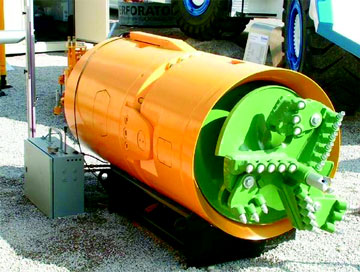
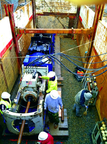
Micro-tunnelling2
Micro tunnelling is a trenchless construction method used to install pipelines beneath highways, railroads, runways, harbours, rivers, and environmentally sensitive areas. Micro-tunnelling is defined as a remotely-controlled, guided, pipe-jacking operation that provides continuous support to the excavation face by applying mechanical or fluid pressure to balance groundwater and earth pressures. Support at the excavation face is a key feature of micro-tunnelling, distinguishing it from traditional open-shield pipe-jacking.
Micro-tunnelling requires jacking and reception shafts at the opposite ends of each drive. The micro-tunnelling process is a cyclic pipe jacking operation. A micro tunnel boring machine (MTBM) is pushed into the earth by hydraulic jacks mounted and aligned in the jacking shaft. The jacks are then retracted and the slurry lines and control cables are disconnected. A product pipe or casing is lowered into the shaft and inserted between the jacking frame and the MTBM or previously jacked pipe. Slurry lines and power and control cable connections are made, and the pipe and MTBM are advanced another drive stroke. This process is repeated until the MTBM reaches the reception shaft. Upon drive completion, the MTBM and trailing equipment are retrieved and all equipment removed from the pipeline.
 |
Most micro-tunnelling operations include a hydraulic jacking system to advance the MTBM and pipe string, a closed loop slurry system to transport the excavated spoils, a slurry cleaning system to remove the spoil from the slurry water, a lubrication system to lubricate the exterior of the pipe string during installation, a guidance system to provide line and grade control, an electrical supply and distribution system to power equipment, a crane to hoist pipe sections into the jacking shaft, and various trucks and loaders to transport spoil off site.
MTBMs have a rotating cutting head to excavate the ground material, a crushing cone to crush larger particles into smaller sizes for transport through the slurry lines, a hydraulic or electric motor to turn the cutting head, a pressurized slurry mixing chamber behind the cutter head to maintain face stability, an articulated steering unit with steering jacks for steering corrections, various control valves, pressure gauges, flow meters, and a data acquisition system. Additionally, the MTBM has inline cameras to relay information to the operator and a target system for guidance control.
Precise control of line and grade is accomplished using the guidance system and steering jacks to locate and steer the MTBM during a micro-tunnelling drive. The guidance system usually consists of a reference laser mounted in the jacking shaft, which transmits a beam onto a target mounted inside the articulated section of the MTBM. This and other operational information is transmitted through wire cables to a control cabin located on the surface.
Micro-tunnelling machines are capable of independently counter-balancing earth and hydrostatic pressures. Earth pressure is counter-balanced by careful control of advance rates and excavation rates of spoil materials. Groundwater pressure is counter-balanced by using pressurized slurry in the soil-mixing chamber of the MTBM.
Rotary Drilling
Rotary drilling is the technique employed in drilling harder clays, gravels, cobbles, and solid rock formations with some sort of drilling head (or drill bit): roller cutters (cylinders or cones), drag-cutting elements (carbide or diamond), or even high-pressure fluid jets.
 |
The principles of rotary drilling are similar to those of previously discussed systems. A hollow drill string, usually made of steel, connects from the drill frame or rig to the end of the hole, where a drill bit is located. For small diameters, two- or three-cone roller bits may be used, or if the rock is hard, drag-type bits with carbide cutters or diamonds may be used. Weight is applied by thrusting the pipe from the drill frame at the surface until the bit is on the bottom with sufficient weight to indent the rock. Rotary motion is imparted, again from the surface drill frame, so that as the bit is rotated it either scrapes or crushes the hard material. Fluid is circulated during this process so that spoil (soil or rock) is washed away from the cutting elements and circulated back to the entrance pit, where the cuttings are removed. The water is usually re circulated.
Bentonite is usually added to the fluid to enhance the following parameters:
- To seal the hole from fluid loss by forming a mud filter cake,
- To improve the lubricating properties of the fluid; and
- To add viscosity helping remove cuttings from the hole.
Oil-field applications of rotary drilling usually employ bits that have nozzles and develop pressure across these nozzles to help clean the rock cuttings from in front of the bit. This is not usually the case in construction applications, where the additional horsepower required to develop the pressure increases the cost of the equipment and its operating expenses beyond the benefit realized.
The rotary drilling or boring rig has four major components:
- Power system
- Driving equipment to move the drill string into or out of the hole as well as to apply thrust or weight
- Rotating equipment for turning the bit and making the hole
- A fluid circulating system to clean and cool the bit and remove the cuttings.
Rotary drilling is more commonly required and used in troublesome areas, such as where cobbles and gravels may be encountered. Also, it is needed for drilling in limestone, sandstone, and shale. The additional torque and thrust capabilities of most rotary-drilling rigs allow adjusting to many of the drilling problems that can occur. These rigs usually have the capability to operate with downhole motors, thus allowing the boring system to be steered.
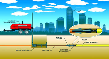
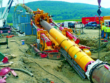
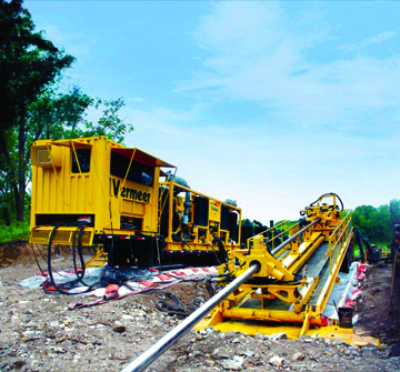
Horizontal Directional Drilling (HDD)4
Horizontal Directional Drilling (HDD) is a trenchless construction method that can be used for bores with diameters as large as 1.4 meters, although diameters less than 1.0 meter are more common. It is a fairly popular trenchless method in India.
HDD can be used to install infrastructure pipes several hundred to a couple of thousand meters long. With this method, an HDD drill rig advances a drill rod generally about 100 to 150 mm in diameter into the ground, creating a pilot bore. The rod is connected to a slanted face steering bit equipped with a sonde that emits electronic tracking signals for tracking from the surface. The bit is steered along a pre-determined bore path by rotating the bit, pushing the bit, or simultaneously pushing and rotating the bit. As the bit face is advance, Bentonite slurry is introduced from inside the drill string to the bit which washes the cuttings back along the outside of the drill string to the pit at the machine insertion side. The pit allows the cuttings to settle out and the slurry is recycled and reused in a closed circuit. The HDD process occurs from the surface and other than the slurry pit no shaft is necessary. As this method is commonly used for an undercrossing, the final bore path profile is generally “U”-shaped. In other words, the rod is inserted at an angle, transitioned to horizontal at the required depth, and then steered upwards to the surface. The radius of curvature for the transition is generally a function of pipe material with a larger radius required for steel pipe than for plastic pipe. The starting angle is generally between 8 and 20 degrees to the horizontal and the exiting angle is generally in the range of 5 to 12 degrees to accommodate the radius of curvature of the pipe when it is pulled back in from the exit side.
 |
At the exit side, a reamer is attached to the pilot rod to enlarge the pilot hole to a diameter that is about 50 percent larger by volume (30 percent by diameter) than the final carrier pipe to be pulled back into the reamed hole. The rig controls the pilot rod such that the reamer is pulled back to the starting point of the bore. Again, the cuttings are flushed back to the insertion pit by introducing slurry through the pipe. Depending on the diameter required for the bore, one or several reaming passes are made with each pass enlarging the diameter of the bore. Depending on the hole size, a final pass is made with a swab to check the hole for stability and to displace material that may have accumulated in the bottom of the reamed hole. Once the required diameter is reached, the final pipeline or conduit is attached to the drill string via a swivel and pulled back through the bored hole.
The final pipeline is generally steel pipe or an engineered plastic, such as PVC or HDPE. Although not as common, ductile iron pipe can be used. Steel and plastic pipe are generally welded into one long string for continuous pullback during installation. The Horizontal Directional Drilling guidelines advocate one continuous pullback during installation to reduce risk associated with stoppages. Ductile iron pipe is generally installed by sections. One consideration in the pipe selection is the space available for assembly. If the length of drill hole is long and the lay down area beyond the exit pit is limited, a sectional pipe assembled at the site may be advantageous. Another area of consideration during the engineering phase is the specification of the radius of the bored path. Care must be taken to ensure that the radius of the bored path is within the pipe manufacturer’s specifications. If the radius of the path is too small or the break over curvature at the pullback is too sharp, for example, the pipe may crack, tear, or buckle thus jeopardizing the integrity of the installation. HDD is typically used with pressure pipelines and electrical conduits where a precise line and grade is not needed.
Pilot Tube Method4
The Pilot Tube Method is one of the newer trenchless methods, having been introduced in the 1990s. It combines benefits of HDD, auger boring, and traditional pipe jacking. The pilot tube is a soil displacement method whose installation is continually monitored by a theodolite aimed on a target at the back of the steering head. The tubes are guided through the ground by means of a Guided Boring Machine (GBM). Pilot tubes are hollow to provide an optical path for the guidance system and double walled to provide a channel for lubricating fluid transfer to the steering head. Once the pilot tubes reach the receiving pit, the guidance system is no longer required.
The LED/camera system allows for highly accurate drives in line and grade and through various ground conditions. The pilot tube can be installed to an accuracy of 3/8 of an inch or better, thus providing a high degree of assurance in maintaining line and grade. An adapter is attached to the last pilot tube to enlarge the tunnel to the diameter of the pipe. The adapter is equipped with a cutter face attached to an auger set inside a casing pipe or the carrier pipe. The cutter face excavates the ground and the auger transports the cuttings back toward the insertion pit or shaft via the pipe used to advance the cutter face. The adapter is advanced through the ground by continually adding pipe sections and jacking the pipe and cutter head forward with the pilot tube providing guidance. As pipe segments are added, pilot tube sections are removed from the receiving pit or shaft. The pilot tube method can install casing pipe or it can direct jack the carrier pipe into place. Suitable pipe diameters range from 102 to 1,200 mm OD.
The drive length of the pilot tubes are a function of soil conditions and generally range from about 80 to 100 m. Longer drives are feasible in soft ground conditions or if lubrication is used. The pilot tube method is generally used in soft to medium stiff or /loose to medium dense ground conditions. Stiff or dense soil conditions can restrict advance of the pilot tube because the ground cannot be displaced readily. The Pilot Tube Method is not applicable to hard soil, ground with cobbles and boulders, or rock.
Trenchless Technology in India
Lack of Awareness about Trenchless Methods
Trenchless Technology as compared to the time-consuming cut-and-cover method of laying utilities across roads disrupting traffic has to be encouraged in India especially in urban scenario. As per the key note address by Sri PP Srivastav, during the NO DIG India Show, 2013, “Trenchless Technology is all the more relevant in hilly terrains where habitations are often interspersed by high-grounds and ridges, something very common in fast growing towns in the North-East and in the Himalayan belt. Strategically placed sensors, cameras etc. along service lines in the hills, can give early indication of ground-displacement, leakage or damage to the utilities. Such information is crucial in the hills where displacement of soil is a precursor of impending landslide disaster. He strongly advocated introduction of Trenchless Technology in hilly regions for two reasons; firstly to ensure that no human habitation remains deprived of civic utilities because of problematic terrain; and secondly to serve as a reliable Early-Warning System as part of pre-Disaster Risk Reduction strategy.
 |
Towards the application aspects, he mentioned that, one step that remains neglected, but is imperative, is mapping (and periodical updating) of all underground utilities in urban centres. The fact of life is that this is generally lacking even in modern cities on account of multiplicity of agencies involved and lack of inter-agency coordination. The result is that laying of a new utility by one agency results in unintended damage to the existing utilities of others. Based on the above he proposed a 2-pronged approached, firstly, training of engineers and others concerned with public utilities in human habitations and also those involved in Disaster Management, especially in the remote Disaster-prone Hill-States of the country; and secondly, a concerted drive to start mapping of existing underground utilities in the existing and growing towns. In the context of training, he referred to the admirable initiative of the NDMA (National Disaster Management Authority) to organise the Great Shillong (1897) Earthquake Simulation Mega-Exercise in mid-February 2014 in the 8 North Eastern States jointly with the State DMAs for which training of different stakeholders has just commenced. He suggested adding-on of Trenchless Technology module, in the training programmes being conducted by NDMA in NE-States and its extension to other vulnerable disaster-prone States.”
Challenges
The primary challenges facing the Indian trenchless market can be summarized as follows:
- Lack of awareness about trenchless methods and their benefits,
- Cost comparisons against cut-and-cover methods that do not take into consideration the evaluation of social costs and benefits,
- A limited pool of specialty contractors skilled in trenchless construction, leading to monopolization of market, and
- Lack of supportive infrastructure.
Conclusion
Under Indian context with the growing population and increasing demands for additional utility services, advanced technologies like Trenchless Technology are inevitable. Especially in over populated urban environment where open trench excavation method is highly undesirable, construction using a trenchless technology is a highly desirable and an excellent alternative. The growing population of many cities in India has necessitated the development of additional utility infrastructures. In areas where soil, groundwater, or urban settings with highly congested infrastructure render open trench excavation highly undesirable, construction using a trenchless technology is an attractive solution. Trenchless technology refers to a variety of underground construction methods that require minimal trenching or surface disrupt
Reference
1. www.indstt.org
2. The International society for Trenchless technology.
3. 'An Introduction to Trenchless Technology' by-Steven R. Kramer, William J. McDonald, James C. Thomson
4. Trenchless Technology - An Overview by: Umesh Dayal, Ph.D.; Nathan J. Ward - Paul C. Rizzo Associates, Inc., Norman Joyal, P.E. G.E.; Glenn Boyce, Ph.D. - Jacobs Associates, Shivam Nigam; Rashmi Gautam - Robbins Tunneling & Trenchless Technology (I) Pvt. Ltd