Concrete Repair
Reactors, Chimneys and Cooling Towers
Buildings and structures have a certain useful life and are normally designed for a specific period of survival generally referred as Design Life of a building. Around us, we come across many structures which have stood the test of time and some structures exhibit distress sign due to variety of reasons including aggressive exposure environment, faulty design, bad workmanship, improper design considerations, overloading and even misuse. Under these conditions repairs and maintenance are of vital importance.
Though detailed investigation and determining the exact cause of distress are the two important pre-requisites, selection of repair material becomes a valuable task in ensuring a durable and trust worthy repair. However, some of the essential parameters for deciding upon a repair material are listed below:
- Low shrinkage properties
- Good bond strength with the base material
- Setting and hardening properties
- Workability
- Compatible coefficients of thermal expansion
- Non Pollutant and Non toxic
- Cost effective
- Low air and water permeability
- Alkaline
- Minimal curing time
- Ability to withstand the movement induced stresses
- Aesthetically good.
In this article some repair aspects in special structures such as Nuclear Reactors, Chimneys, and cooling Towers are described.
Concrete Repairs in Nuclear Reactors
In general, the durability of nuclear power plant safety-related concrete structures is high. However, the causes generally can be related either to improper material selection or construction/design deficiencies. Examples of some of these problems include low concrete compressive strengths, voids under the post-tensioning tendon bearing plates, cracking of post-tensioning anchor heads, containment dome delaminations, misplaced steel reinforcement, post-tensioning system button-head deficiencies, and water-contaminated corrosion inhibitors.
Degradation Mechanisms
Exposure to the environment (e.g., temperature, moisture, cyclic loadings, etc.) can produce degradation of reinforced concrete structures. The rate of deterioration is dependent on the component's structural design, materials selection, and quality of construction, curing, and aggressiveness of environmental exposure. Termination of a component service life occurs when it no longer can meet its functional and performance requirements.
 |
Primary mechanisms (factors) that, under unfavorable conditions can produce premature deterioration of reinforced concrete structures include those that impact either the concrete or steel reinforcing materials (i.e., mild steel reinforcement or post-tensioning systems). Degradation of the concrete can be caused by adverse performance of either its cement-paste matrix or aggregate materials under chemical or physical attack. In nearly all chemical and physical processes influencing the durability of concrete structures, dominant factors involved include the transport mechanisms within the pores and cracks, and the presence of water. Degradation of mild steel reinforcing materials can occur as a result of corrosion, irradiation, elevated temperature, or fatigue effects, with corrosion being the most likely form of attack. Post tensioning systems are susceptible to the same degradation mechanisms as mild steel reinforcement plus loss of prestressing force, primarily due to tendon relaxation, and concrete creep and shrinkage.
Material Performance in Nuclear Reactors
Nuclear safety-related concrete structures are composed of several constituents that, in concert, perform multiple functions (e.g., load-carrying capacity, radiation shielding, and leak tightness). Primarily, these constituents include the following material systems: concrete, conventional steel reinforcement, prestressing steel, steel liner plate, and embedment steel. Data on the long-term performance of the reinforced concrete materials is of importance for demonstrating the durability of the nuclear power plant concrete structures and in predicting their performance under the influence of pertinent aging factors and environmental stressors. This information also has application to establishing limits on hostile environmental exposure for these structures and to the development of inspection and maintenance programs that will prolong component service life and improve the probability of the component surviving an extreme event such as a loss-of-coolant accident.
In-service Inspections
In-service inspection programs are conducted to help ensure that the nuclear power plant structures have sufficient structural margins to continue to perform in a reliable and safe manner. A secondary goal is to identify environmental stressors or aging factor effects before they reach sufficient intensity to potentially degrade structural components. Routine observation, general visual inspections, leakage-rate tests, and destructive and nondestructive examinations are techniques available to identify areas of nuclear power plants that have experienced degradation. Determining the existing performance characteristics and extent and causes of any observed distress is accomplished through a structural condition assessment that routinely initiates with a general visual inspection to identify suspect areas followed by application of destructive or nondestructive examinations to quantify the extent and significance of any observed degradation.
Nondestructive Examinations
Application of nondestructive examination methods to nuclear power plant reinforced concrete structures presents challenges: wall thicknesses can be in excess of one meter; structures often have increased steel reinforcement density with complex detailing; there can be a number of penetrations or cast-in-place items; accessibility may be limited due to the presence of liners or other components, harsh environments, or structures may be located below ground; experience with nondestructive examinations of nuclear power plant concrete structures is somewhat limited; and methods utilized for the nuclear power plant structures are often based on equipment developed for other materials or technologies. Available methods are relatively good at identifying cracking, voids, and delaminations, and indicating the relative quality of concrete. Methods for determining concrete properties, however, are somewhat more qualitative than quantitative because they tend to be indirect in that they often require the development of correlation curves for relating a measured parameter (e.g., ultrasonic velocity or rebound number) to a property (e.g., concrete compressive strength). Identification and description of methods for determining the strength of concrete and evaluation of concrete structures is provided elsewhere. A practical guide related to nondestructive examination of concrete has been developed that not only identifies and describes the capabilities, limitations, and applications of the various methods that are available, but presents results from a number of examples.
 |
Noninvasive techniques for characterization, inspection, and monitoring of thick-walled, heavily reinforced concrete structures in nuclear power plants to provide additional assurances of their continued structural integrity are desirable (e.g., as-built or current structural features determination, flaw detection and characterization, identification of honeycomb areas and embedded items, and location of voids adjacent to the liner). Methods that can be used to inspect the basemat without the requirement for removal of material and techniques that can detect and assess corrosion are of particular interest. Acoustic (e.g., ultrasonic pulse velocity, spectral analysis of surface waves, impact echo, and acoustic tomography), radar, and radiography appear to have potential for this application; however, additional development is required.
The most commonly used type of foundation for both concrete and steel nuclear power plant containments is a mat foundation, which is a flat, thick slab supporting the containment, its interior structures, and any shield building surrounding the containment. As such, the concrete foundation elements of nuclear power plants are typically either partially or totally inaccessible for inspection. Under conditions such as this the foundation structures are only accessible for inspection after removal of adjacent soil, coatings, waterproof materials, or portions of neighboring components or structures. As a result, indirect methods related to environmental qualification are often utilized to indicate the potential for degradation of the nuclear power plant concrete foundations. This is generally done through an evaluation of the surrounding medium (e.g., air, soil, humidity, groundwater, or cooling water).
Remedial Methods
Deterioration of reinforced concrete generally will result in cracking, spalling, or delamination of the cover concrete. Whenever damage is detected, corrective actions are taken to identify and eliminate the source of the problem thereby halting the degradation process. A remedial measures strategy is formulated based on the consequence of damage (e.g., affect of degradation on structural safety), time requirements for implementation (e.g., shutdown requirements, immediate or future safety concern), economic aspects (e.g., partial or complete repair), and residual service life requirements (e.g., influences action taken). Basic guidance on the repair of degraded structures is available. Improved guidance, however, is desired relative to assessment of defects (e.g., cracks) as well as information on the performance and effectiveness of subsequent repairs (e.g., durability of repair materials).
Applications of Structural Reliability Theory
If properly designed and constructed, the concrete structures in nuclear power plants generally have substantial safety margins; however, additional investigations to establish available margins of degraded structures are desired. In addition, improved understanding of how age-related degradation may affect dynamic properties (e.g., stiffness, frequency, and dampening), structural response, structural resistance/capacity, failure mode, and location of failure initiation is desired to provide additional assurance that the current licensing basis is maintained under all loading conditions.
 |
Decisions as to whether to invest in maintenance and rehabilitation of structures, systems, and components as a condition for continued service and risk mitigation, and the appropriate level of investment, should consider the nature and level of uncertainties in their current condition and in future demands. Recent advances in structural reliability analysis, uncertainty quantification, and probabilistic risk assessment make it possible to perform such evaluations and to devise uniform risk-based criteria by which existing facilities can be evaluated to achieve a desired performance level when subjected to uncertain demands. Reliability-based approaches have been applied to the nuclear power plant concrete structures and in evaluation of the prestress level in concrete containments with unbonded tendons.
 |
Degradation effects can be quantified with fragility curves developed for both undegraded and degraded components. Fragility analysis is a technique for assessing, in probabilistic terms in the presence of uncertainties, the capability of an engineered system to withstand a specified event. Fragility modeling requires a focus on the behavior of the system as a whole and, specifically, on things that can go wrong with the system. The fragility modeling process leads to a median-centered (or likely) estimate of system performance, coupled with an estimate of the variability or uncertainty in performance. The fragility concept has found widespread usage in the nuclear industry, where it has been used in seismic probabilistic safety and/or margin assessments of safety-related plant systems. The fragility modeling procedures applied to degraded concrete members can be used to assess the effects of degradation on plant risk and can lead to the development of probability-based degradation acceptance limits. This approach has been applied to a limited extent to degraded flexural members and shear walls. Additional work is desired in this area for the purpose of refining and applying the time-dependent reliability methodology for optimizing in-service inspection/maintenance strategies and for developing and evaluating improved quantitative models for predicting future performance (or failure probability) of a degraded concrete structure, either at present or some future point in time.
 |
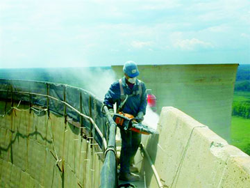
Chimneys and Cooling Towers
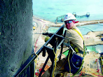
Reinforced concrete chimneys are high-rise and slender specialized structures. They are normally built by specialists to high standards of engineering with strict quality control of the concrete. Traditionally, concrete chimneys were not provided with any additional surface protection. For many years site assembled precast concrete sections or continuous slip-forming concrete on site were used in chimney construction. However, even with strict quality control it is always likely that there will be some site difficulties, e.g. during the concrete placement, finishing or assembly, some elements will move out of place and form voids, suffer grout loss, reduce cover thickness or be physically damaged.
The use of high-strength concrete with its relatively low slump-flow or flowability also means that it can be difficult to compact. By nature and shape of the structure, the freshly placed concrete in these structures on site is always difficult to cure correctly.
Chimneys are very exposed to aggressive influences on their external surfaces due to the exposed locations where these structures are built, their height above nearby structures and of course their function. The internal surfaces are normally fully lined or channelled and therefore protected.
The aggressive external influences include:
- Atmospheric carbonation
- Frequent wetting and drying
- Freeze-thaw cycles (the result of increased wind chill)
- High thermal variations and thermal gradients in sunlight
- Chlorides from marine atmospheres (even miles inland due to prevailing winds)
- Exhaust gases and condensates
- Influencing of neighboring chimneys
The potential for concrete damage from these exhaust gases containing varying levels of acidic sulphurous (SOx), nitrous (NOx) and other aggressive materials is probably the greatest overall threat, even when modern flue gas desulfurization equipment is fitted.
Cooling Towers
Cooling towers are used to remove excess heat that is generated in places such as power stations, chemical plants and even domestically in air conditioning units. In power stations, electricity is generated when steam drives a turbine. This steam must be condensed before it can be returned to the boiler to continue the cycle of steam and electricity generation. The condensation process happens in a heat exchanger.
Cooling water is needed in the heat exchanger and it is this cooling water that is cycled through the cooling tower. In this way the water for the boilers and steam turbine is kept separate from the cooling water. This stops impurities getting into the turbine steam.
Concrete Maintenance
All things deteriorate over time. Even structures constructed of reinforced concrete require maintenance in order to continue to function as a critical foundation support asset. Cooling Tower structural elements are no different except that the concrete can provide a foundation, containment for cooling process fluids or housing critical mechanical equipment. Cooling towers fall into two main categories: Natural draft and Mechanical draft.
Natural draft towers use very large concrete chimneys to introduce air through the media. Due to the large size of these towers, they are generally used for water flow rates above 45,000m3/hr. These types of towers are used only by utility power stations.
Mechanical draft towers utilize large fans to force or suck air through circulated water. The water falls downward over fill surfaces, which help increase the contact time between the water and the air - this helps maximise heat transfer between the two. Cooling rates of Mechanical draft towers depend upon their fan diameter and speed of operation.
Regardless of whether the Cooling Tower is based on Natural Draft or Mechanical Draft Technology, deterioration in aggressive environments are generally time dependent as long as regularly scheduled maintenance is performed and changes to the process are minimal. However, the only constant in life is 'change' and these changes can provide wide swings in available service life as well as the assumption that the structure was constructed in accordance with industry 'Best Practices'.
Unfortunately original construction practices, poor quality materials of construction, harsh environmental service exposure conditions as well as changes to process streams can culminate in premature failure in structural performance. Understanding these deterioration trends, well in advance of deficient structural behavior, is the goal of every Owner. Tools, in line with "Risk Based Inspection" (RBI) Programs developed for mechanical and electrical systems, are also available for civil assets. These tools provide indications as to the present condition of the structure and assist in prioritizing Maintenance/Repair Programs, allowing Owners to capitalize maintenance budgets over extended periods of time.
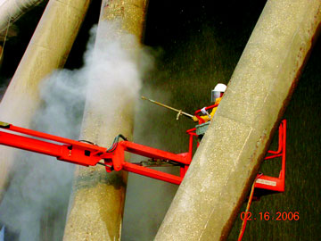
Large reinforced concrete, natural draught cooling tower structures can be as tall or even taller than many chimneys. However, due to their design and function, they have a very much larger surface area with a much lower mass to surface area ratio.
Unlike chimneys, both the internal and external concrete surfaces of cooling towers are exposed to aggressive influences. The external exposure and the potential damage are therefore similar but the internal surfaces are usually in much greater danger.
The External Exposure
The external surfaces are exposed to very similar aggressive influences like chimneys. However, due to their much larger circumference and diameter with a much lower mass to surface area, they are at much greater risk of cracking. This is due to settlement and adverse thermal gradients developing from thermal variations imposed on the surfaces.
The Internal Exposure
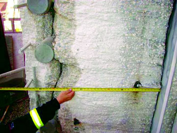
The internal surfaces of cooling towers are also very large and exposed. Even though they are constructed with acid-resistant concrete, it has been recognized that they must be given additional surface protection. This is due to their direct exposure and contact with the exhaust gases and condensates, which are often aggressive and acidic at a pH as low as 2.5.
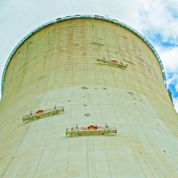
The successful repair, protection and corrosion management of reinforced concrete chimneys and cooling towers always requires an initial professional assessment and an appropriate detailed condition survey. Some access and even some refurbishment works can take place while these structures are in service. But inspection and assessment work of external zone 1 and most of the internal surfaces of cooling towers, which are integral part of the power production, can normally only be done during switch off, boiler servicing or upgrading works.
The costs of any extended closure or downtime are extremely high, due to the complex national grid infrastructures, power transmission changes and the other works required. This will always lead to great time pressure, to complete the project on time. However, it is essential that a full professional assessment is carried out prior to repair and protection works.
To do otherwise is short-term and a false economy, as serious structural damage could follow, possibly putting the structure completely out of commission for a long period and endangering people and other structures in the vicinity. The second stage is the design, execution and supervision with technically correct repair "principles" and "methods", using products and systems which for optimum results and long-term cost effectiveness, should be selected according to the industry standards.
Scheduling Planned Cooling Tower Maintenance
Assuming structures are "built-to-specs", as all things built by man degrade over time, regularly planned inspections and maintenance should be incorporated into the operating budget for an asset, including Cooling Towers and their associated concrete elements. As much of the access to view the internal status of Cooling Towers are predicated on drained basin conditions, many times an inspection will identify "discovery" deterioration with repair opportunities noted but not acted upon due to time limitations. In cases such as these, planned maintenance during a future scheduled outage can be prudent and provide an opportunity for the Owner to secure funding for the necessary maintenance. The kinds of potential reinforced concrete maintenance issues associated with an operating Cooling Tower can include:
- Leaking cracks in the reinforced concrete Walls and Base Slab
- Adhesion/cohesion Joint Sealant failures
- Embedded Waterstop leakage
- Expansion Joint deterioration and leakage
- Mechanical penetration leakage
- Anchor Bolt corrosion
- Lack of foundation support for the Cooling Tower superstructure
- Embedded reinforcing steel bar corrosion and resultant structural member spalling
- Erosion of concrete surface paste
- Differential settlement of the Cooling Tower Basin Wall/Base Slab
- Algal growth and vegetation obstruction
History and experience have shown that each Cooling Tower Structure poses unique challenges to a Repair Contractor. Regardless of whether the required repair involves partial or full-depth structural member section repairs, foundation stabilization, containment liner, crack repair or simply stopping cooling water egress, it's imperative to utilize an engineered solution. A proper repair strategy should consist of:
- Identifying and determining the root-cause of failed concrete/structural elements
- Employing proper materials in construction and repair techniques
- Using a qualified experienced Contractor who can provide a solution, as well as a well-planned Quality Assurance/Quality Control (QA/QC) program for the repair
- Location, Qualification and Quantification (LQQ) of Deterioration
Should significant distress conditions be exposed during a regularly scheduled maintenance outage, an evaluative approach, as discussed earlier, should be initially employed:
- Locate the deterioration
- Qualify the distress mechanisms and determine the "root-cause"
- Quantify the amount of repair to assess repair methodology - determine whether to Repair or Replace-in-Kind
Concrete deterioration comprises both obvious and latent characteristics that are not easily understood without gathering further information through investigation. Employing a combination of Non-Destructive (NDT) and Semi-Destructive Testing (SDT) techniques, characterizations as to the physical and chemical properties of the reinforced concrete structures can be determined quickly. Using cutting-edge analytical and diagnostic tools, the evaluator establishes these repair parameters:
- An evaluation that investigates further, and qualifies causes & effects;
- A quantification of the problem that expresses its extent in concrete terms (e.g. square feet, cubic feet, linear feet, etc.)
- Documentation describing where the distressed conditions are located – and what it will cost to repair them – arranged from highest to lowest priority.
Once adequately characterized, a thoughtful and detailed repair approach can be developed addressing thermodynamic, chemical and construction material properties of the structure operating within the Cooling Tower process service environment - optimally resulting in a long-term repair program.
Corrosion of Concrete Structures in Coastal Areas
Reinforced concrete structures in marine environments often deteriorate prematurely in the early stages of service life. When structures are in their infancy, the high alkalinity of concrete forms a passivating layer on embedded steel reinforcement, providing protection from corrosion.
However, when concrete structures are constantly submerged in saltwater and exposed to salt spray, chloride ions penetrate concrete, eventually breaking down this passivating layer to initiate corrosion. This process occurs most rapidly in the splash zone where there is sufficient oxygen to facilitate corrosion and the intermittently wet and dry conditions exacerbate chloride penetration. Moisture present in the concrete also increases the electrical conductivity, leading to rust pitting – an aggressive form of localised corrosion. This causes rapid loss of steel sections with consequent cracking and spalling of concrete.
In tidal and submerged zones where the concrete is saturated, oxygen levels are limited as concrete pores are constantly filled with water. However, in areas of low concrete cover, corrosion can still occur, causing a challenge for reinstatement.
Cracking in concrete structures and corrosion of the embedded reinforcing steel are costly problems. The coastal salt laden air carries highly alkaline chloride ions from sea water as far as two miles inland. These chloride ions saturate concrete structures such as parking structures, commercial buildings, and bridges, destroying the ferric oxide coating that protects the reinforcing steel, resulting in the expansion of the steel and usually causing the surrounding concrete to crack.
New Technology
Solving complex problems like these is a highly specialized field requiring the understanding of several professional disciplines; structural and materials engineering, chemistry, and familiarity with materials from the coating and corrosion industry.
When a concrete spall or fracture is cut out and a patch made with new concrete is installed, an electrochemical reaction occurs just like in an alkaline battery and corrosion is accelerated adjacent to the patched area. The "incipient battery effect", as it's called, results from new concrete, free of chloride ions and with its' normal very high alkalinity (ph 12.6-13.2), coming into contact with the surrounding chloride saturated concrete that has lost alkalinity over time due to calcium hydrate leaching from the concrete (ph 9.0 to 12.0).
The incipient battery effect must be counteracted with corrosion control technology or the repair will not be durable (typical lifecycle of 1 to 3 years). Corrosion control technology has improved dramatically with the recent advent of chemical corrosion inhibiting materials, each for a specific combination of environmental factors and concrete chemistry.
Coastal structures exhibiting signs of distress in the form of cracking or spalling should be evaluated by engineers familiar with corrosion mechanics to locate and quantify the various forms of distress, test the chemistry of the concrete and determine the cause of the problem.
Concrete Evaluation, Repair and Restoration
Achieving a long-lasting restoration begins with formulating a complete repair strategy. This requires an accurate diagnosis of the damage and its determining underlying cause, selection of the right repair process, materials, and methods, and protecting the repair and remainder of the building from future deterioration.
Repair: A repair strategy must be based on economic reality and value based alternatives should be presented in terms of their initial cost, annual cost, and expected life-cycle. A comprehensive cost analysis sometimes indicates it is more economical to totally replace balconies and walkways than to repair them.
When the repair strategy has been selected, specifications for repair or replacement can utilize repair procedures published by the International Concrete Repair Institute. The specifications should provide material requirements, thicknesses, tolerances, and acceptance standards, as well as comprehensive general and supplemental conditions designed to protect the owners interests and keep the Contractor fully responsible for risks. The completed project manual should include submittal requirements, test data required to monitor the contractor's performance, and the Contractor's quality control requirements.
Protecting: To protect the repair and the remainder of the building, water-proofing coatings, sealants, and high density premium grade protective paints and caulk should be specified that allow concrete to reduce concrete carbonation and keep out chloride ions. Some new water-proof coatings combine modest flexibility and still allow concrete to breath, thereby reducing the potential for blistering or coating disbondment from entrapped moisture. The Owner should engage a representative who is capable to verify the work is performed as contracted. The Owner's representative can test materials used to verify they meet specification requirements and observe construction to document it's conformance to specifications and building standards.
The Optimum Solution
Solutions that offer technologically advanced reinstatement mortars specifically for marine can be used and cementitious coatings to provide long-term protection in hostile coastal environments. These mortars and coatings are resistant to early wash-out and afford optimum performance in wet, chloride-laden environments. Suitable for both remedial works and new build projects, application can be undertaken on damp substrates between tides. Such products will cure normally under water to form a durable, impenetrable barrier to chlorides whilst also preventing the ingress of oxygen and carbon dioxide in reinforced concrete exposed to the atmosphere.
References:
http://www.structural.net/article/cooling-tower-concrete-maintenance
http://flexcrete.com/sectors/coastal-structures/reinforced-concrete-structures/
http://www.towertechinc.com/concrete-cooling-towers/Concrete_Specification_02232012.pdf
http://www.beeindia.in/energy_managers_auditors/documents/guide_books/3Ch7.pdf
http://unitedengineeringconsultants.com/wp-content/uploads/2011/02/corrosion-article.pdf
https://www.sika.com/.../design_support_concrep_chimneys_cooling_to...