Precast Technology
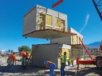
The concept of precast construction includes those buildings where the majority of structural components are standardized and produced in plants in a location away from the building, and then transported to the site for assembly.
|
| The concept of precast construction includes those buildings where the majority of structural components are standardized and produced in plants in a location away from the building, and then transported to the site for assembly. |
Success of a precast building project is an integration of all involved building professionals including architects, engineers, clients, contractors and sub-contractors. The involvement of all these key players right from the conceptual stage is critical and of vital importance to any precast project. In the present day context, consultants are concerned with clients' needs, regulatory requirements, design soundness and functionality while clients are more concerned with cost and the end product. Contractors, on the other hand, are more concerned with the building process and implementation of technology effectively.
Several projects have been created by architects and structural designers using precast concrete technology as one of the fast track construction techniques to meet the challenges of present day demands. Innovative projects as diverse as stadiums, bridges, parking structures, offices, schools, housing and industrial buildings have been produced. These designers have not only expanded the ways in which precast concrete was used, but have also devised new techniques embraced by the entire design community.
The concept of precast construction includes those buildings where the majority of structural components are standardized and produced in plants in a location away from the building, and then transported to the site for assembly. These components are manufactured by industrial methods based on mass production in order to build a large number of buildings in a short time at low cost.
This type of construction requires a restructuring of the entire conventional construction process to enable interaction between the design phase and production planning in order to improve and speed up the construction. One of the key premises for achieving that objective is to design buildings with a regular configuration in plan and elevation.
India is facing acute shortage of skilled and unskilled manpower especially in the construction industry. The demand-supply chain severely affected and broken beyond repairs at this juncture and the construction speed has drastically come down.
Urban residential buildings of this type are usually five to ten stories high. Many countries used various precast building systems during the second half of the 20th century to provide low-income housing for the growing urban population. In general, precast building systems are more economical when compared to conventional multi-dwelling residential buildings in many countries.
Necessity of Precast in India
India is facing acute shortage of skilled and unskilled manpower especially in the construction industry. The demand-supply chain severely affected and broken beyond repairs at this juncture and the construction speed has drastically come down. On the other hand, increasing urban population, impetus given by the Government, Favorable FDI policies, multi-nationals coming into the industry with new technologies, have given rise to innovative building construction methods like Pre Engineered Metal Buildings, Prefabrication of elements in the Structural Steel, Concrete and composite structures. Following three important factors can be attributed to this shift. Figure shows Demand-Supply Projections for 2011-2015 in Housing Units (In Thousands) - data sourced from Cushman & Wakefield Research.
 |
- Rapid increase in construction activity.
- The growth development in the form of High and medium scale Industries, IT development centered around the major cities of India, owing to the good Transportation means in the form of Air, Rail, and other means of Travel and communication , energy facilities, etc.
- Consequently, increase in urban population as employment opportunities have been created in these locations, and in turn, the requirement of Office space, Commercial space, and consequently demand for residential units in the form of multi-story Apartments, Gated communities, Independent villas, etc.
Advantages of Precast Construction
- Enables use of pre-tensioning techniques, reducing cost and increasing spans.
- Improves handling ability.
- Economy in formwork by repetitive use.
- Speed of production from rationalisation and standardization of design.
- Greater quality control in all facets of production, because work takes place under cover allowing optimum and shorter concrete curing conditions independent of climate.
- Shorter on-site times as factory production proceeds ahead of site construction.
- Dimensional accuracy.
- Precast elements may be prestressed to achieve greater strength requirement and load bearing capacity.
- Large floor spans
- Extremely good fair-face concrete finish.
- Mechanisation and Mass Production.
- Walls with Insulation possible.
- Less wastage
- Ease of construction
- Better health and Safety Standards
- Economical for large and repetition projects.
- Longer life and durability
Disadvantages
- Advance meticulous planning required.
- Requirement of Casting / Stacking - Large Space
- Detailed joints & connections - Micro Details
- Restriction on size & weight - transportation
- Deployment of Plant and Machinery - Initial High Investment
- Less suitable for Buildings with irregular features
Construction Considerations
Following important factors to be kept in mind, while constructing buildings with precast technology.
- Safety issues when handling precast elements.
- Lifting capacity of the crane.
- The working boom-radius of the crane.
- The suitability of construction materials for the purpose of use, i.e. sealant, grouting, shim plate, propping etc
- Co-ordination with the pre-caster and specialist supplier to achieve the best performance and working method - pre-caster often provide relevant technical requirements to the contractor during the design development phase to avoid discrepancy.
Categories of Precast Building Systems
Depending on the load-bearing structure, precast systems described can be divided into the following categories: Large-panel systems, Frame systems, Slab-column systems with walls And, Mixed systems.
The use of linear elements generally means placing the connecting faces at the beam-column junctions. The beams can be seated on corbels at the columns, for ease of construction and to aid the shear transfer from the beam to the column.
|
|
| Precast wall structure compared to RCC frame structure has some added advantages like - No Brickwork or Block work, No Plastering, Saving in Labour, Thin Walls increase Carpet area and more Durable. |
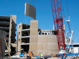
Large-Panel Systems
The designation "large-panel system" refers to multistory structures composed of large wall and floor concrete panels connected in the vertical and horizontal directions so that the wall panels enclose appropriate spaces for the rooms within a building. These panels form a box-like structure. Both vertical and horizontal panels resist gravity load. Wall panels are usually one story high. Horizontal floor and roof panels span either as one-way or two-way slabs. When properly joined together, these horizontal elements act as diaphragms that transfer the lateral loads to the walls.
Depending on the wall layout, there are three basic configurations of large-panel buildings:
- Cross-wall system-The main walls that resist gravity and lateral loads are placed in the short direction of the building.
- Longitudinal-wall system-The walls resisting gravity and lateral loads are placed in the longitudinal direction.
- Two-way system-The walls are placed in both directions.
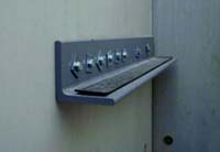
Thickness of wall panels ranges from 100 mm for interior walls to 300 mm for exterior walls. Floor panel thickness varies from 60 mm to 200 mm. Wall panel length is equal to the room length, typically on the order of 2.7 m to 3.6 m. In some cases, there are no exterior wall panels and the faade walls are made of lightweight concrete. A typical interior wall panel is shown in Figure.
Panel connections represent the key structural components in these systems. Based on their location within a building, these connections can be classified into vertical and horizontal joints.
Vertical joints- connect the vertical faces of adjoining wall panels and primarily resist vertical seismic shear forces.
Horizontal joints- connect the horizontal faces of the adjoining wall and floor panels and resist both gravity and seismic loads.
Depending on the construction method, these joints can be classified as wet and dry.
Wet joints- are constructed with cast-in-place concrete poured between the precast panels. To ensure structural continuity, protruding reinforcing bars from the panels (dowels) are welded, looped, or otherwise connected in the joint region before the concrete is placed.
Dry joints- are constructed by bolting or welding together steel plates or other steel inserts cast into the ends of the precast panels for this purpose. Wet joints more closely approximate cast-in-place construction, whereas the force transfer in structures with dry joints is accomplished at discrete points.
Frame Systems
Precast frames can be constructed using either linear elements or spatial beam-column sub-assemblages. Precast beam-column sub-assemblages have the advantage that the connecting faces between the sub-assemblages can be placed away from the critical frame regions; however, linear elements are generally preferred because of the difficulties associated with forming, handling, and erecting spatial elements.
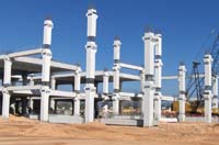
The use of linear elements generally means placing the connecting faces at the beam-column junctions. The beams can be seated on corbels at the columns, for ease of construction and to aid the shear transfer from the beam to the column. The beam-column joints accomplished in this way are hinged. However, rigid beam-column connections are used in some cases, when the continuity of longitudinal reinforcement through the beam-column joint needs to be ensured. The components of a precast reinforced concrete frame are shown in Figure.
The load-bearing structure consists of a precast reinforced concrete space frame and precast floor slabs.
The space frame is constructed using two main modular elements: a cruciform element and a linear beam element. The cruciform element consists of the transverse frame joint with half of the adjacent beam and column lengths. The longitudinal frames are constructed by installing the precast beam elements in between the transverse frame joints. The precast elements are joined by welding the projected reinforcement bars (dowels) and casting the concrete in place. Joints between the cruciform elements are located at the mid-span of beams and columns, whereas the longitudinal precast beam-column connections are located close to the columns. Hollow-core precast slabs are commonly used for floor and roof structures in this type of construction, as shown in Figure.
Precast wall structure compared to RCC frame structure has some added advantages like- No Brickwork or Block work, No Plastering, Saving in Labour, Thin Walls increase Carpet area and more Durable.
Slab-Column Systems with Shear Walls
These systems rely on shear walls to sustain lateral load effects, whereas the slab-column structure resists mainly gravity loads. There are two main systems in this category:
• Lift-slab system with walls
• Prestressed slab-column system
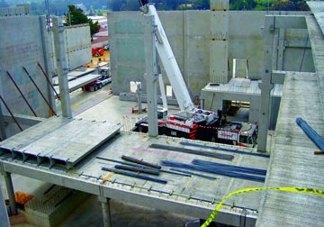
In the Lift-slab system the load-bearing structure consists of precast reinforced concrete columns and slabs, as shown in Figure. Precast columns are usually two stories high. All precast structural elements are assembled by means of special joints. Reinforced concrete slabs are poured on the ground in forms, one on top of the other. Precast concrete floor slabs are lifted from the ground up to the final height by lifting cranes.
The slab panels are lifted to the top of the column and then moved downwards to the final position. Temporary supports are used to keep the slabs in the position until the connection with the columns has been achieved. In the connections, the steel bars (dowels) that project from the edges of the slabs are
Welded to the dowels of the adjacent components and transverse reinforcement bars are installed in place. The connections are then filled with concrete that is poured at the site.
Most buildings of this type have some kind of lateral load-resisting elements, mainly consisting of cast-in-place or precast shear walls, etc. In case lateral load-resisting elements (shear walls, etc.) are not present, the lateral load path depends on the ability of the slab-column connections to transfer bending moments. When the connections have been poorly constructed, this is not possible, and the lateral load path may be incomplete. However, properly constructed slab-column joints are capable of transferring moments as shown by several full-scale vibration tests performed on buildings of this type.
Another type of precast system is a slab-column system that uses horizontal prestressing in two orthogonal directions to achieve continuity. The precast concrete column elements are 1 to 3 stories high. The reinforced concrete floor slabs fit the clear span between columns. After erecting the slabs and columns of a story, the columns and floor slabs are prestressed by means of prestressing tendons that pass through ducts in the columns at the floor level and along the gaps left between adjacent slabs. After prestressing, the gaps between the slabs are filled with in situ concrete and the tendons then become bonded with the spans. Seismic loads are resisted mainly by the shear walls (precast or cast-in-place) positioned between the columns at appropriate locations.
| Reinforced concrete slabs are poured on the ground in forms, one on top of the other. Precast concrete floor slabs are lifted from the ground up to the final height by lifting cranes. |
|
|
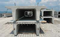
Modular System
In case of smaller single units, this system is helpful. Some of the advantages are;
- Entire unit is cast in a factory and installed at site.
- Suitable for toilet blocks or individual rooms.
- Monolithic casting guarantees waterproofing at junctions.
Components of PC System
Beams-Horizontal members that support deck components such as double tees and hollow-core slabs, beams typically are considered structural components. Three types cover the majority of uses: rectangular beams, inverted tee beams, and L-beams.
Precast Columns and Beams http://www.tekla.com/ae/Documents/model-comp-2011/images/pics/precast_ranco_2.jpg
 |
Columns- Columns typically support cross members such as beams, spandrels, or panels. Traditionally square or rectangular in profile, they are usually cast as multilevel components ranging in length from a single story to multi story. |
| Double Tees - These components are used primarily as deck, floor, and roof components, contributing in large part to precast concrete's ability to create long spans and open interior plans. They can be used for any type of building but most often are used in parking structures, office buildings, and industrial facilities. |
 |
Hollow-core slabs are used in a wide range of buildings as floor/wall components. These include multifamily and single-family housing, schools, hotels, health-care centers, offices, manufacturing facilities, and other structures. Hollow-core slabs typically measure 150mm to 300mm thick, but they can be made as thin as 100mm or as thick as 400mm. Long hollow cores, or voids, run the entire length of each piece, giving the material its name.
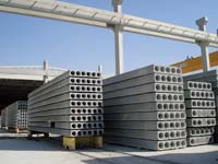 |
A Hollow core slab is a precast, prestressed concrete member with continuous voids provided to reduce weight, and therefore cost, and as a side benefit to use for concealed electrical or mechanical runs. They are primarily used as floor or roof deck systems. Other applications include- wall panels, Spandrel members and bridge Deck units. |
Strand used in hollow core is low relaxation strand of 12.7 mm (1/2 inch) diameter and keyway grout is normally a sand and Portland cement mixture in proportions of about 3:1.
Advantages of Hollow Core Slabs
Structurally, a hollow core slab provides the efficiency of a prestressed member for:
- Better load capacity
- Span range and deflection control
- Speed of construction
- Optimum use of material
- High quality of appearance and finishes
- High quality of control achievement at one location
- In addition, a basic diaphragm is provided for resisting lateral loads by the grouted slab assembly provided proper connections and details exist.
- Excellent fire resistance up to 4 hour endurance
- The sound transmission class ratings ranges from about 47 - 57 without topping and the impact insulation class rating starts at about 23 for plain slabs and may be increased to over 70 with the addition of carpeting and padding.
- When properly coordinated for alignment, the voids in a hollow core slab may be used for electrical or mechanical runs. Slabs used as the heated mass in a passive solar application can be detailed to distribute the heated air through the pores.
- Hollow core Slabs can span for a range of 16 - 20 meters considering the load conditions and the overall thickness of the slab varies as: 150, 200, 250, 265, 300, 320, 400 mm etc., depending upon the core size used by the different manufacturers.
- High strength concrete of grade not less 35 N/mm2 is used in the hollow core slab in order to gain early strength and lift it from the bed.
- If steam curing is adopted, the slab can be lifted from the casting bed in about 8 to 10 hours including the casting time and then it will be shifted to the precast yard for further curing for about 3 days, and eventual shifting to the building site.
Wall Panels- Precast concrete wall panels are versatile components that can be used as architectural, structural, or combination elements within a building's design. Wall panels can be designed as load bearing or non-load bearing components. Non-load bearing panels can be attached to any type of structural frame, including precast concrete, cast-in-place concrete, or steel. They can be erected in a horizontal position, as in a multifamily housing or office application, or in a vertical position, typically used in warehouse designs.
http://blog.highconcrete.com/wp-content/uploads/2012/09/100608-Montclair-0681024x7681.jpg
Sandwich Wall Panels-Insulated sandwich wall panels typically include two inch or more of high-performance insulation between two layers of concrete. This configuration provides high energy efficiency and an interior concrete wall that can be finished, avoiding the need for a finish treatment of furring strips and drywall. Precast concrete's high thermal mass also minimizes energy consumption naturally.
In addition to aesthetics, precast panels can be manufactured with built-in insulation material, reducing the thermal U-value dramatically, and thereby improve the cost of running the building as reduced A/C capacity
is obtained. This also creates a balanced comfortable and healthy in-door climate. Standard thicknesses of sandwich panels are 200, 250, 270 and 300mm.
Mullions- As the name implies, mullions are support pieces inside a larger void space that typically produce a decorative, geometric appearance. These pieces can create right-angle designs, or they can be cast at angles, producing a decorative grille effect. These thinner pieces are cast into the overall panel, reducing the number of pieces and providing faster installation than if a different material is used for the dividers or grille work.
Raker Beams- Raker beams are beams cast with an angled surface with right-angled notches spaced along the top surface. The beams are used as support members for single-, double-, and triple-row stadium risers.
Shear Walls- Shear walls provide a solid concrete, standalone structural brace that is typically used in total precast concrete and parking structures. It provides support throughout interior spaces to handle overhead spanning components and to counter lateral loads on the structure. These components are designed to withstand wind and seismic loads. In some cases, they are designed with central voids to provide light and ventilation.
Spandrels- Spandrels consist of horizontal members, typically of less height than a traditional floor-to-floor architectural panel. These panels are used in a variety of applications to meet structural-support and architectural needs in parking structures and as cladding for office buildings with long expanses of windows.
In load bearing designs, these units include an interior ledge, which can support deck components such as double tees and hollow-core slabs. Load bearing designs also can include pockets cast into the thickness of the spandrel, into which the stem of a double tee fits. Non-load bearing designs are used as cladding for a wide range of buildings.
Superior Concrete for casting
Self-Consolidating Concrete
Self-consolidating concrete (SCC) incorporates high-range water-reducing admixtures that significantly increase the material's workability and fluidity. As a result, it flows quickly into place, fills every corner of a form, and surrounds even densely packed reinforcement. The two key attributes of self-compacting concrete are its high degree of workability and its stability during and after placement. In general, setting time requires 30 to 90 minutes longer than conventional concrete. Accelerating or retarding admixtures can be used to produce concrete with the desired setting characteristics.
A variety of advantages can be derived from the use of SCC that benefits the casting. These include:
High quality - Because the material flows so readily to fill any gaps, no voids or "bug holes" develop. This reduces the time needed to inspect each component, as well as any labor or time to rub the pieces redundant to create a smooth finish. It produces an aesthetically superior finish;
Aesthetic value-The smooth finish that can be created produces an aesthetically pleasing component without any additional finish. SCC also produces a consistently lighter color with reduced discoloration;
Speed-Because SCC flows so smoothly, it can be poured quickly and eliminates the need to vibrate the concrete into tight spaces and around densely packed reinforcement. That expedites the entire production process. The speed with which it gains strength also eliminates the need for steam or heat curing of concrete to facilitate early strength gain. SCC will create fast turnaround and reduced cycle times;
Design flexibility-Because SCC flows so readily into thin sections and details, it opens the potential for using complex shapes and intricate surfaces. SCC works particularly well with vertical components that include obstructions to the form at the top, such as tall columns with blockouts. It alleviates concerns about aggregate reaching the bottom of the form and not segregating due to obstructions. It also ensures no patching of holes after casting or potential damage to pieces during vibration. This is especially significant for delicate panels, such as those with brick insets;
Durability-The material's ability to remain stable during and after placement maximizes the structural integrity and durability of the concrete. The admixtures provide a higher compressive strength than traditional concrete, making it substantially stronger. It also offers less permeability due to the high consolidation of material, allowing it to resist chemical attack and improve the component's durability. It provides a high modulus of elasticity, ensuring low elastic deformation of the concrete under dynamic and static loads.
Ultra-High-Performance Concrete (UHPC)
|

|
| Ultra-high-performance concrete (UHPC) consists of steel fiber-reinforced, reactive-powder concrete that provides a compressive strength of about 200 MPa, more than twice that of any high-performance concrete used to date. |
Ultra-high-performance concrete (UHPC) consists of steel fiber-reinforced, reactive-powder concrete that provides a compressive strength of about 200 MPa, more than twice that of any high-performance concrete used to date. The basis for its enhanced properties is a mix design specifically engineered to produce a highly compacted concrete with a small, disconnected pore structure. Eliminating coarse aggregate and substituting finely ground powders creates the structure. This combination minimizes the paste-aggregate bond-failure mechanism that limits the strength of typical high-performance concretes.
The material also includes fine sand, quartz flour, and steel or organic fibers measuring 1/2 in. long and 6 mm in diameter. These fibers are responsible for much of the tensile strength and toughness of the material. UHPC provides significant postc racking strength due to the large number of fibers in the matrix confining the material.
The incredible strength of the UHPC components means that component designs need to be altered to take advantage of the material's abilities. Current designs allow space for significant strand, for instance, and using UHPC could change the typical stout, compact shape to a thinner and lighter design. The best shapes to maximize the material's use are still being studied and will depend on specific applications.
Architectural concrete
The architectural applications of precast concrete are extensive. With few limitations on shape and a wide range of finishes and mould textures at their disposal the designers can express their own style and give character to their designs. Architectural precast concrete is employed as decorative wall panels, window frames, stairs or feature walls (structural), non-structural wall panels, and in fact all exterior concrete that contributes to the visual effect of the building. This concrete can range from the lower cost plain panels to the more expensive textured or exposed aggregate faced units.
|

|
| The use of fly ash, slag and other waste materials aid in reducing a buildings environmental footprint. Precast's high durability produces buildings with a total service life that outpaces other systems or materials. |
Sustainable Design
Precast concrete offers a number of benefits that make it environmentally friendly and also meet the goals of programs such as Leadership in Energy & Environmental Design. Precast concrete buildings can be designed for disassembly and adaptability, and are easily deconstructed for reuse at the end of a building's life.
Precast's energy efficiency, reduction in materials, recyclability, reusability and ability for repurposing, along with minimal waste in the precast plant and on the jobsite, are keys to meeting environmental standards. In addition, with building codes requiring higher energy efficiency, integrated solutions using hollow core slabs for heating and cooling is a growing trend in building design that reduces energy consumption. With precast's ability to aid in meeting LEED™ standards, other benefits such as thermal mass become more apparent to designers.
The use of fly ash, slag and other waste materials aid in reducing a buildings environmental footprint. Precast's high durability produces buildings with a total service life that outpaces other systems or materials.
Precast concrete demonstrates comparable environmental impact performance over alternative structures.
Concrete Grades
- The concrete is usually made with normal aggregates and Ordinary Portland Cement. For faade units, special aggregates and white Portland cement with colour pigments may be used.
- M50 Or More for Pre-stressed beams, columns, slabs, pre-stressed hollow-core units
- M45: For Products in reinforced concrete
- Special units, for example columns or beams, can be made in high strength concrete, grade M80.
Standards, Guidelines
- IS 456 2000
- Australian National Code Of Practice For Precast, Tilt Up & Concrete Elements In Building Construction
- EN 13369 Precast Concrete and Precast Products
- CEN/ TC 229 "Precast concrete product standards"
- FIP Commission on Prefabrication, "FIP Recommendations Precast Pre-stressed Hollow Core Floors"
- FIP Commission on Prefabrication, "Planning and design handbook on precast building structures"
- fib Commission on Prefabrication, Guide to good practice "Special design recommendations for precast pre stressed hollow-core floors"
Fire Resistance
- For industrial buildings, the normal required fire resistance of 30 to 60 minutes is met by all types of precast components without any special measure.
- For other types of buildings, a fire resistance of 90 to 120 minutes is obtained by increasing the reinforcement cover.
- Based on the requirements in Eurocode 2, Part 1-2 "Structural fire resistance"
Check List
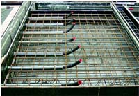
Formwork
- That unless otherwise specified, only steel forms and steel or concrete bottom forms are used for standard members. Voids for beams are polystyrene.
- The forms, bulkhead, spacers, spreader bars, and other equipment having a bearing upon the accuracy of dimensions of the completed beams. The inspector informs the producers of any discrepancies observed and overviews the necessary corrections.
- The alignment of forms before and during the casting operation. Joints between soffit, side forms and bulkheads are tight and leak proof. Plugging of holes and slots in the forms is neatly done so that the finished member has a favorable appearance.
- The void forms are anchored firmly and securely braced in their final position. The thickness of the bottom layer of concrete shall be checked before placing the voids.
- The position of the void is maintained both vertically and laterally during concrete placement. The concrete cover over each void is measured as soon as the surface is finished to discover any dislocations of the voids, with suitable gauges or probes.
- The air vents are installed prior to concreting.
- Forms are treated with an approved form release agent.
- Any strand or reinforcement found contaminated with a bond breaking substance is properly cleaned prior to placing concrete.
 |
Prestressing Steel
- Prestressing steel is domestic and free of deleterious materials such as grease, oil, rock, clay, dirt, paint and loose rust. Strands which exhibit rust that cannot be removed by wiping with a dry cloth are not used.
- Prestressing tendons or strands having kinks, bends, nicks or other defects are not used.
- Tensioned strand are not subjected to excessive temperatures produced by torches, welding equipment or sparks.
- Strands are positioned as shown on the shop drawings.
- Ducts or voids provided in the concrete for longitudinal post-tensioning tendons are formed by means of flexible PVC or metal conduit, metal tubing or other approved means or void forms are completely sealed against leakage of mortar and properly anchored in position. Lateral post tensioning tubes shall be non-flexible PVC material or other material if approved by the Engineer.
- No more than one approved splice per strand is used.
- Multiple strand tensioning has all of the strands spliced or no more than 10% of them. If all of the strands are spliced, the average splice slippage should be considered in computing the elongation. If 10% or less are spliced, no slippage allowance is required.
- Splices are not located within the concrete members.
 |
| De-tensioning immediately follows the curing period required by the specifications and when test cylinders indicate the required strength is obtained. During detensioning operations the prestressing forces are kept symmetrical about the vertical axis of the member and applied in such a manner as to prevent any sudden (shock) loading. |
Stressing
- The stress induced in the prestressing steel is measured both by gauges, and by elongation of the tendons and/or load cells as specified.
- Approved certified pressure gauges, load cells, dynamometers or gauging devices are used and re-calibrated at least once a year. Discrepancies between measured elongations and gauging measurements in excess of specifications should be carefully checked and the source of error determined and corrected before proceeding further.
- The copies of reports are reviewed for each manufacturing operation recorded by the fabricator's Quality Control representative.
Pre-tensioning
- To check the casting beds and pallets periodically for deviation from a plane surface.
- To verify the initial tensioning force.
- To verify the proper marking of reference points prior to and after the initial tensioning forces have been applied to the strands, i.e., tape on strands and paint marks.
- To note changes in the ambient temperature and verifies that the proper adjustment is made to elongation for fixed abutment beds.
- Check for slippage of strand anchorages.
- Check the actual dimensions of the bed layout and locations of hold-up and hold-down points to see if they agree with the dimensions shown on the approved shop drawings within the allowable tolerances. Approved hold-up and hold-down devices as shown on the shop drawings are attached in such a manner as to maintain the specified center-to-center spacing of strands in both the vertical and the horizontal directions.
- Check for size and location of mild steel reinforcement and that minimum concrete cover is obtained including hold-down devices remaining in the beams.
 |
De-tensioning
- Forms, over yokes, hold-down, etc., which may restrict either horizontal or vertical movement of Prestressed members are stripped, or at least loosened, prior to de-tensioning. De-tensioning immediately follows the curing period required by the specifications and when test cylinders indicate the required strength is obtained. During de-tensioning operations the prestressing forces are kept symmetrical about the vertical axis of the member and applied in such a manner as to prevent any sudden (shock) loading.
- All strands are released simultaneously by hydraulic jacking. The total force is taken from the header by the jack, and then gradually released. With this method, some sliding of the members on the beds is inevitable.
- The strands are released by heating and gradually cutting the strands in accordance with the posted pattern. Cutting is performed simultaneously at both ends of adjacent members. De-tensioning patterns are approved by the fabricator's Engineer.
Concrete Tests
- General tests, i.e., slump, air and temperature are conducted on the same batch of concrete, independently from the plant's quality control tests. The inspector performs 10% air and slump testing, and molds two 28-day cylinders per test based on the frequency of testing conducted by the plant, or one test per week at a minimum. Four inspection cylinders per test will be molded at prestressed facilities.
- Compression tests of molded cylinders are used to determine the time of de-tensioning in addition to the 28-day concrete strengths.
- Samples are carefully selected and are representative of all the concrete placed in the beam. Samples are taken approximately from the middle third of the batch or from a chute which is under full flow of concrete.
- Cylinders are made, marked and handled in accordance with the approved Quality Control plan.
- Cylinders are marked in accordance with the approved Quality Control plan and stored adjacent to the casting bed during accelerated curing and then follow the product for the full curing and storage cycles.
- The compressive strength of the concrete at stress transfer is determined by testing cylinders cured with the concrete members. Cylinder molds are required to be steel to prevent deformation during accelerated curing.
- Cylinder molds are stripped at the same time as member forms are stripped.
 |
Slump and air content tests are made in accordance with the Quality Control plan. Slump flow and J-ring tests are performed whenever Self Consolidated Concrete (SCC) is used. Stability of the mixture is visually assessed. Mixtures having a visual stability index greater than 1.0 are rejected. |
Vibration of Concrete
- Concrete in members is compacted by the use of external and/or internal mechanical vibrators. SCC mixtures which were not qualified for vibration during the trial batching and evaluation phase may not be vibrated.
- Vibration is not prolonged until it caused segregation of the materials.
- Sufficient vibrators to complete the compaction are used.
- Vibration is performed at the point of deposit and in the area of freshly deposited concrete. The internal vibrators are moved about in the freshly deposited concrete and across the junctions between succeeding batches of concrete so that the entire mass will be thoroughly and uniformly compacted. Internal vibrators are not pushed rapidly but allowed to work themselves into the concrete mass and withdrawn slowly to avoid the formation of air voids.
 |
Cold joints in the concrete are not accepted. If delays are encountered, concrete which has set so long that it will not receive a vibrator easily is to be completely removed from the form, if possible, or the member rejected. |
Curing of Concrete
- Special attention is given to the proper curing of all fresh concrete. Concrete is protected so that moisture is not lost during the early stage of hydration.
- The curing procedure is established and carefully controlled. Concrete is kept continuously moist until the conclusion of the specified curing period.
- After placing and vibrating, the concrete is required to attain initial set before steam is applied so that the concrete has sufficient strength to resist cracking due to thermal expansion. The length of the delay period between the finishing of the concrete and the application of the steam varies according to the mix design.
- Steam curing is completed under a suitable enclosure to contain the live steam and minimize moisture and heat losses.
- Recording thermometers showing the time-temperature relationship throughout the entire curing period are located at a spacing not to exceed 100' of the bed. The ambient temperature is verified with hand thermometers. Temperature recording charts are retained as a part of the permanent records
Transportation
- Prestressed concrete beams are transported in an upright position in accordance with specifications.
- Storage areas are flat and firm, and beams are not twisted.
- Prior to storage, beams are given a complete inspection for tolerances, camber, cracks, bearing area, stirrup placement, alignment, recessed strand areas are patched, open drains, patched vents, etc. Verification of camber must be performed not more than two weeks prior to shipment.
- Necessary corrections are made prior to inspector approval for partial payment or shipment.
- The inspector's stamp of approval is placed on each accepted beam. Indelible ink is used for stamping
- Rejected members are properly identified.
Uneven Creep and Shrinkage during Storage
If a concrete component is stored for a long period in a situation where the sun or wind acts predominantly on one side of the member, the creep and shrinkage effects will vary across the member, resulting in distortions which can cause problems during installation. Components such as long precast beams and match-cast precast deck segments are particularly sensitive to this. It is therefore preferable to store such members in an orientation which results in uniform sun and wind exposure.
Poor stacking of precast elements can also cause the lower, more highly stressed elements to deform more due to creep. This often occurs when component s are stacked with incorrectly positioned timber spacers.
Site monitoring staff should ensure that the contractor's storage and support arrangements are approved. This applies especially to precast beams where incorrect temporary support points may adversely affect the stresses in the beam.
Erection
Erection preparation
Consideration should be given to the following items to ensure safe and efficient installation of the precast elements in accordance with the design intent:
- Assembly and erection method;
- Concrete strength or age requirements;
- Permanent structural connection and joint details; and
- Propping and temporary support details.
If the sequence of erection is critical to the structural stability of the structure, or for access to connections at certain locations, it should be noted on the drawings. The erection drawings, which should include all relevant information, should be prepared prior to the commencement of any erection
Erection safety
Safety during the handling and erection of precast concrete elements is of paramount importance and compliance with the relevant current regulations is required.
All equipment used for the handling and erection of a precast element must be maintained to a high standard, load tested as necessary, and be suited to the intended use.
Consideration should also be given to the site environment particularly with regards to built up areas and implications this may have on erection safety.
Erection sequence
Precast elements should be erected in accordance with a pre-planned sequence as detailed in the erection drawings. This sequence of erection should be such that the multiple handling of elements is minimized. A trial erection operation should be considered to identify any unforeseen erection difficulties.
Missing or damaged lifting inserts
If missing, faulty or incorrectly located lifting inserts are identified, the designer should be contacted immediately to assess the problem and decide on an alternative lifting system. It should be verified, where permanent fixings or connections are temporarily used during construction, that the fixings are suitable for the temporary use and their long-term performance will not be compromised.
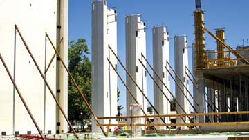
Temporary bracings
Precast concrete elements must be adequately braced and supported during all phases of erection to ensure proper alignment and structural integrity until permanent structural connections have been completed. The design of temporary bracing and supporting structures should comply with the approved erection plan. The installation and erection is to be in accordance with the approved drawings and checked by a competent person as set out in the project's Site Safety Supervision Plan. Wherever possible bracing should be fixed to the element before lifting. When it is necessary to attach the braces after the element has been positioned, the element should not be detached from the crane until the braces have been installed. Bracing bolts should be checked at regular intervals to ensure that they are secure and undamaged.
Propping
All temporary propping requirements must be shown on the erection drawings. The design of temporary propping systems should be in accordance with the erection plan. Consideration should be given to the following:
- Propping that supports beams should accommodate possible changes to the distribution of loads during the construction process;
- The seating of precast beams may not be adequate to transfer high loads during construction and precast beams will normally require full propping at each end;
- If the structural design requires beams to be supported without the use of mid-span props (to reduce the end support dead load bending moments) this requirement must be clearly noted on both the contract drawings and the precast layout drawings;
- Where beams have floor systems placed on them prior to the beams being fully built into the structure, the beams may not be evenly loaded by the floor units during construction. Long span floor units placed on one side only of a beam may cause the beam to roll on the props. In such circumstances each edge of the beam may require separate temporary propping;
- All temporary propping should be in place, adjusted to the correct levels allowing for any required cambers, and fully braced prior to commencement of erection of any precast beams, unless specific provision has been made to do otherwise;
- Temporary propping should provide full support for all construction loads including the full self weight of the completed floor system and possible local concentrations of load during construction, unless specifically noted otherwise;
- Required duration of propping time and sequence of de-propping;
- All temporary propping should be in place, adjusted to the correct levels allowing for any required cambers, and fully braced prior to commencement of erection of any floor units, unless specifically noted otherwise;
- Props should be vertical and braced to prevent side-sway of the whole assembly and the buckling of individual props.
Acknowledgement:
The above article has been compiled for readers benefit from many sources and presentations by leading technocrats. References to the following have been extensively made.
1. Precast Concrete Construction-by Svetlana Brzev, British Columbia Institute of Technology, Canada and Teresa Guevara-Perez,
Architect, Venezuela.
2. PCI Manual-Designing with Precast and Prestressed concrete.
3. Presentation made by S A Reddi, Fellow Indian National Academy of Engineering at Vizag.
4. Presentation made by Prasad, Managing Partner, PS Engineering Consultants, at Vizag.
5. Precast Manual, Department of Transportation, Pennsylvania.
6. COP for Precast Concrete Construction-2003